Cooling-heating-electricity cogeneration compressed air energy storage system

A technology of compressed air energy storage and electricity connection, which is applied in the field of energy storage and can solve problems such as danger, harsh geographical conditions, and large land occupation

Inactive Publication Date: 2019-11-08
STATE GRID CORP OF CHINA +4
View PDF8 Cites 6 Cited by
  • Summary
  • Abstract
  • Description
  • Claims
  • Application Information

AI Technical Summary

Problems solved by technology

For example, the geographical conditions for station construction are strict. The upper reservoir is built on the top of a large mountain with strict requirements on height, area, and geological structure. The lower reservoir also occupies a large area, and there are specific requirements for water sources and road traffic; The cycle is long, for example, the installed capacity is 1.8 million KW, the investment is 6.5-9 billion yuan, and the construction period is 6-8 years; it needs to occupy a large area of ​​land and cause damage to the ecological environment. Taking 1.8 million kW as an example, the construction site covers an area of ​​4000- 5,000 mu, the engineering volume includes the upper and lower reservoirs, water diversion pipes, diversion pipes, winding roads, diversion canals, etc.; there are still certain risks in the operation of the power station, such as earthquakes, landslides, storms, debris flows, rock weathering, dam cracks, thermal Expansion, cold contraction, rupture, etc. will bring fatal danger

Method used


Image

  • Cooling-heating-electricity cogeneration compressed air energy storage system

Examples


Embodiment Construction

[0040] The specific implementation manners of the present invention will be further described in detail below in conjunction with the accompanying drawings and embodiments. The following examples are used to illustrate the present invention, but are not intended to limit the scope of the present invention.

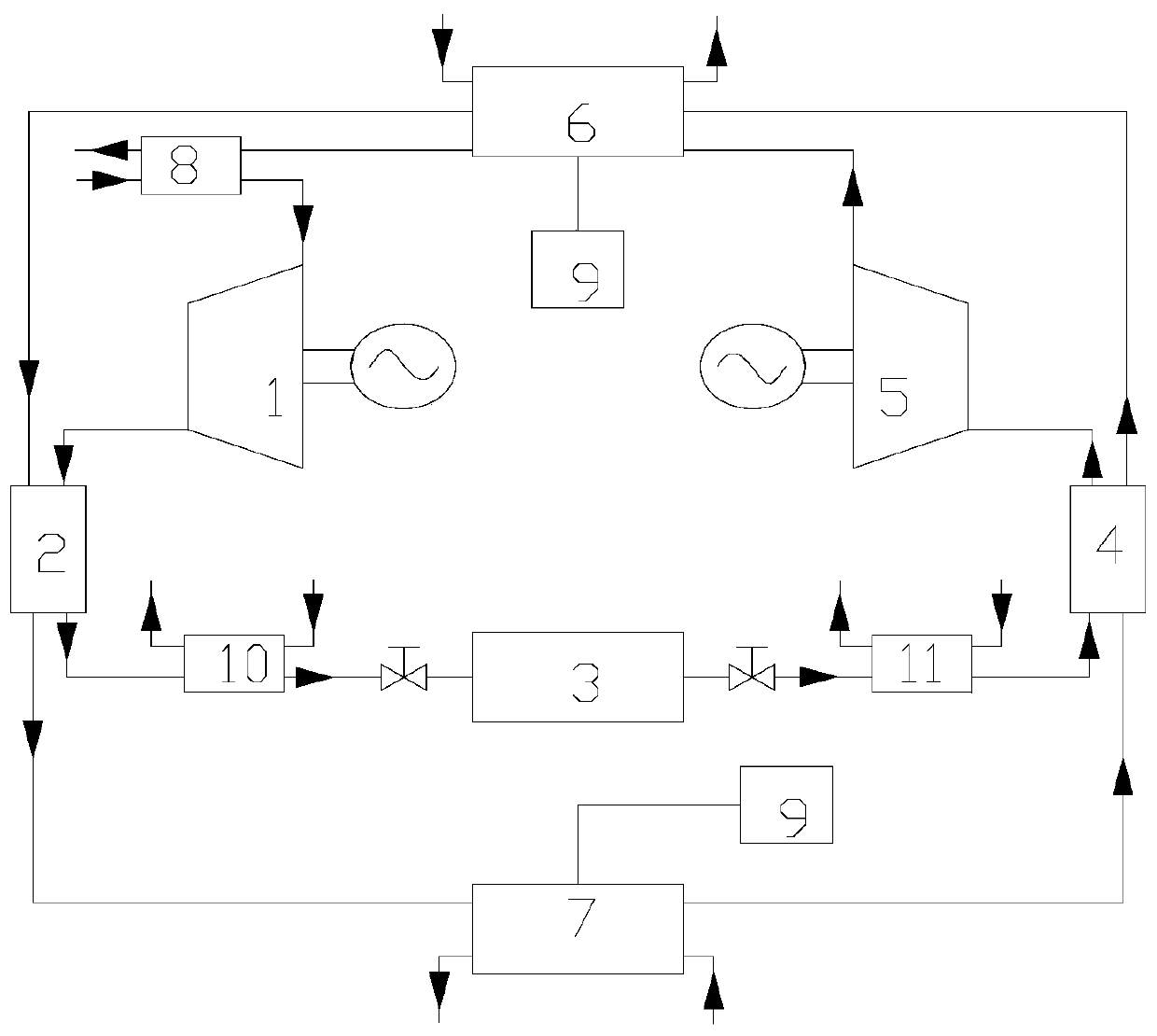
[0041] Such as figure 1As shown, the cold-heat-electric compressed air energy storage system of the present invention includes: a compressor unit 1, a gas storage device 3, a turbine unit 5, a precooler 8, a subcooler 10, a preheater 11 and a heat conduction unit Mass cycle, heat conduction working medium cycle includes cooler 2, heat regenerator 4, cold storage device 6, heat storage device 7 and pressurization system 9; compressor unit 1 uses electric energy to compress air into high-pressure compressed air, and the gas storage device The air inlet of 3 is connected with the air outlet of compressor unit 1, and the air storage device 3 stores the air compressed by compr...


PUM


Abstract

The invention relates to the field of energy storage and discloses a combined cooling, heating and power compressed-air energy storage system. In the energy storage mode, according to the system, electric energy is consumed by the aid of a compressor set, compressed air is stored in an air storage device, and heat produced in the compression process is recovered by the aid of a cooler and is stored in a heat storage device; in an energy releasing mode, according to the system, the air in the air storage device is heated by the aid of a regenerator, a turbine generator set is driven by the hotair to generate power, and cold produced in the expansion process is stored in a cold storage device; in the heating mode, according to the system, heat is supplied to the outside of the system by theaid of the heat storage device; and in the cooling mode, according to the system, cold is supplied to the outside of the system by the aid of the cold storage device. The system can run in the singlemode or run in a multiple-mode-mixed manner. Meanwhile, the system can recover heat sources such as industrial waste heat, waste heat, solar energy and the like by the aid of a preheater or the heatstorage device, or the system can recover the cold such as industrial waste cold, LNG gasification and the like by the aid of an after-cooler or the cold storage device, and the simple system is usedfor meeting the diversified energy requirements.

Description

technical field [0001] The invention relates to the field of energy storage, in particular to a cold-heat-electricity combined compressed air energy storage system. Background technique [0002] Energy storage, especially electric energy storage, is of great significance to the optimization of energy structure and the regulation of power grid operation. The invention proposes an economically feasible, pollution-free, multi-interface, and widely-used energy storage technology, which provides a solution for solving the problem of large-scale integrated storage of traditional electric power and renewable energy. Pumped storage is currently the most widely used and mature energy storage method. According to statistics in 2008, pumped storage accounts for 99% of the total installed capacity of international energy storage systems; conventional compressed air energy storage systems account for 0.5%, ranking second . Energy storage systems such as batteries, flywheels, and superc...

Claims


Application Information

Patent Timeline
Patent Type & Authority Patents(China)
IPC IPC(8): F04B41/02F04B39/06F01D15/10F01K3/18
CPCF01D15/10F01K3/18F04B39/06F04B41/02Y02E60/16
Inventor 梅生伟薛小代陈晓弢司杨宋洁
Owner STATE GRID CORP OF CHINA
Why Eureka
Try Eureka