
Building with multifunctional rope reeling-off equipment
A multi-functional and equipment technology, applied in life-saving equipment, fire rescue, building rescue, etc., can solve problems such as incomplete fire-fighting facilities, fire-fighting and escape resistance, affecting rescue and fire-fighting speed and efficiency, etc.
- Summary
- Abstract
- Description
- Claims
- Application Information
AI Technical Summary
Problems solved by technology
Method used
Image

Examples
Embodiment Construction
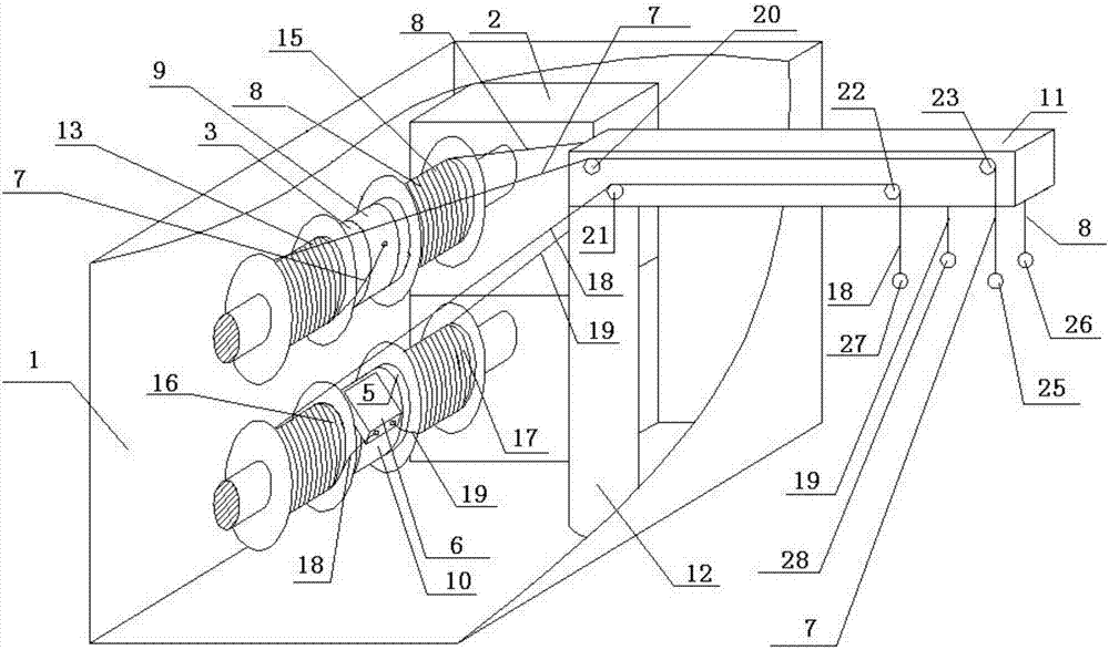
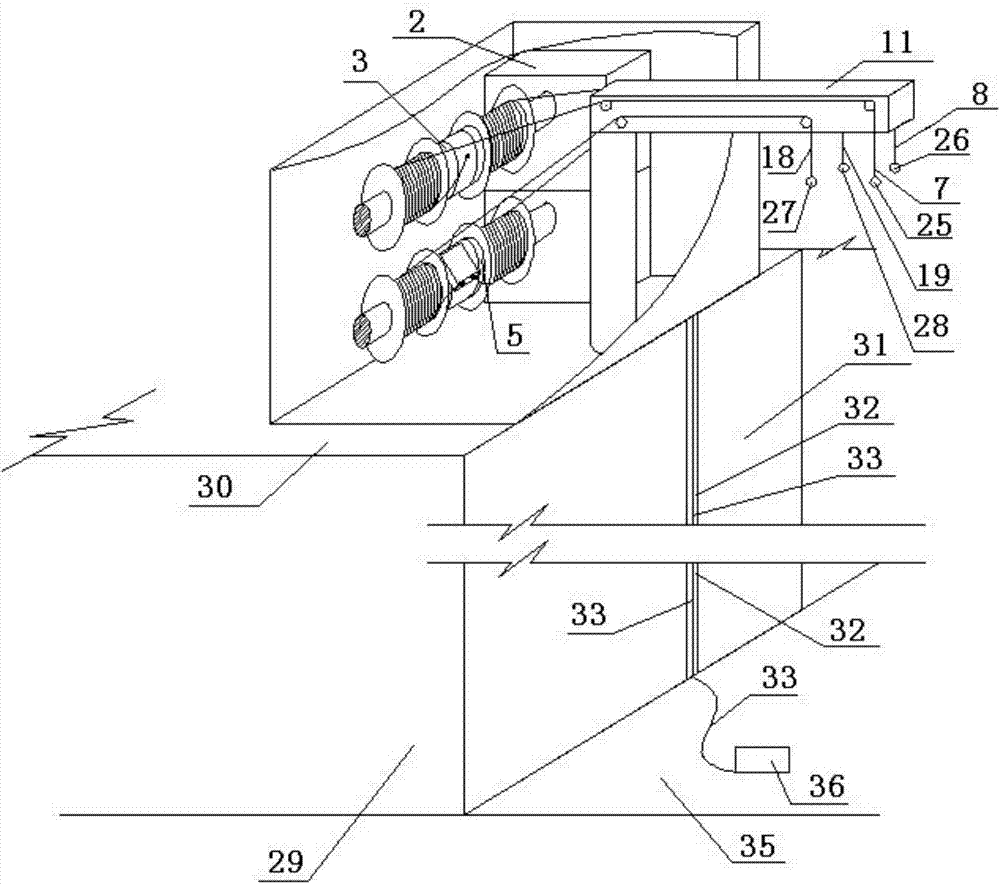
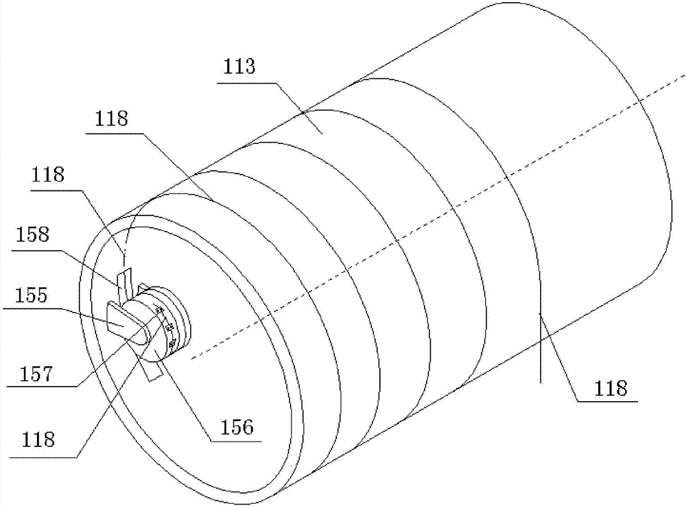
[0084] Such as figure 1 as shown, figure 1It is a schematic oblique view of the multifunctional rope releasing device according to the first embodiment of the present application. The multifunctional rope-releasing equipment includes a housing 1, a motor 2, a rotating shaft 3, a rotating shaft 5, a slow descender 6, a pull rope 7, a pull rope 8, a rotating body 9, a rotating body 10, a cantilever 11, and a column 12, Above-mentioned electric motor 2, rotating shaft 3, rotating shaft 5, descender 6, stay cord 7, stay cord 8, rotating body 9, rotating body 10, column 12 are arranged in the casing, and motor 2 and rotating shaft 3, rotating shaft 5 The connection can drive the rotating shaft 3 and the rotating shaft 5 to rotate. The above-mentioned rotating body 9 is sleeved on the outer circumference of the rotating shaft 3 and can rotate in one direction around the rotating shaft 3. The above-mentioned rotating body 10 is sleeved on the outer circumference of the rotating sh...
PUM
 Abstract
Description
Claims
Application Information