Temperature senor and washing machine

A technology of temperature sensor and resistive core, which is applied in other washing machines, washing devices, textiles and papermaking, etc., can solve the problems of small electrical distance, high production cost, complicated production process, etc., and reduce production conditions, simplify production process, temperature Transmission even effect

Active Publication Date: 2018-05-11
SUZHOU SAMSUNG ELECTRONICS CO LTD +1
View PDF4 Cites 0 Cited by
  • Summary
  • Abstract
  • Description
  • Claims
  • Application Information

AI Technical Summary

Problems solved by technology

[0005] Due to the above production process, it can be seen that the existing temperature sensor has many production steps, which makes the production process more complicated.
In addition, the above-mentioned production process takes five hours, which makes the production efficiency of the temperature sensor low; the above-mentioned production process requires high temperature, which makes the production conditions of the temperature sensor relatively high, resulting in high production costs
[0006] In addition, in the process of epoxy potting, more air bubbles are likely to be generated, and the air bubbles will make the temperature transmission uneven, resulting in the sensory drift of the resistor core 14
[0007] In addition, water vapor easily enters the sensor along the wire 13. Since the resistance core 14 is not waterproof, the water vapor will cause the sensory drift of the resistance core 14.
[0008] In addition, since the existing temperature sensor uses wires 13 side by side, the electrical distance between two adjacent wires 13 where they are welded to the terminals of the resistance core 14 is relatively small, and short circuits are more likely to occur.

Method used


Image

  • Temperature senor and washing machine
  • Temperature senor and washing machine
  • Temperature senor and washing machine

Examples


Embodiment Construction

[0036] The following will clearly and completely describe the technical solutions in the embodiments of the present invention with reference to the accompanying drawings in the embodiments of the present invention. Obviously, the described embodiments are only some, not all, embodiments of the present invention. Based on the embodiments of the present invention, all other embodiments obtained by persons of ordinary skill in the art without making creative efforts belong to the protection scope of the present invention.

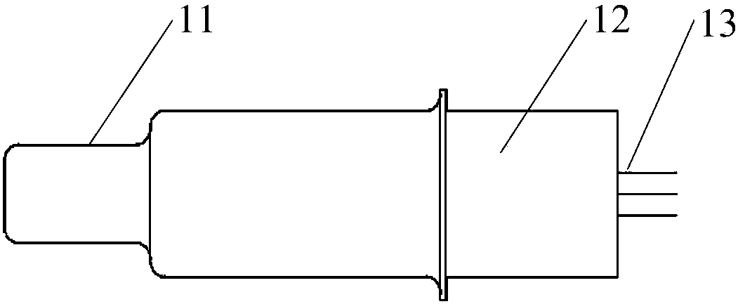
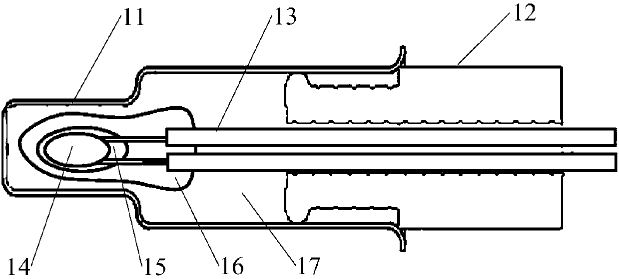
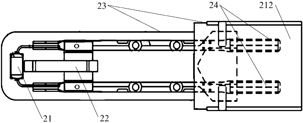
[0037] Such as Figure 3-5 As shown, the temperature sensor provided by the embodiment of the present invention is molded by injection molding.

[0038] It should be noted that the temperature sensor includes a resistance core 21 and a lead-out piece connected to the resistance core 21 , the above-mentioned temperature sensor is molded by injection molding, and the resistance core 21 and the lead-out piece are molded by injection molding. The temperature sens...


PUM


Abstract

The invention discloses a temperature sensor and a washing machine. The temperature sensor is formed through injection-molding sealing. The temperature sensor comprises a resistance core, a draw-forthpart and an injection-molding body, wherein the draw-forth part is connected with terminals of the resistance core, and comprises a first-segment draw-forth part and a second-segment draw-forth partwhich are connected with each other, and the first-segment draw-forth part is connected with terminals of the resistance core; the injection-molding body is subjected to injection-molding sealing outside the resistance core and the first-segment draw-forth part, an avoidance cavity is formed in the injection-molding body, and the second-segment draw-forth part is located in the avoidance cavity. By means of the temperature sensor, through injection-molding sealing forming, the steps of a manufacturing technology are omitted, and thus the manufacturing technology is simplified; meanwhile, the manufacturing technology takes few minutes, and the production efficiency of the temperature sensor is effectively improved; the inject-molding sealing technology does not need high temperature either,the manufacturing condition of the temperature sensor is lowered, and thus the production cost is lowered; bubbles cannot be generated in the injection-molding sealing forming process, and sensing drifting of the resistance core due to the presence of the bubbles is avoided.

Description

technical field [0001] The invention relates to the technical field of temperature measurement, and more specifically, to a temperature sensor and a washing machine. Background technique [0002] The temperature sensor is a commonly used temperature measuring device. In order to measure the temperature of the liquid medium, the temperature sensor is required to have sealing performance. For example, a washing machine with a heating function needs to detect the water temperature in the tub of the washing machine, and control the heater of the washing machine according to the water temperature. [0003] At present, temperature sensors with sealing performance are molded by epoxy sealing. Specifically, such as Figure 1-2 As shown, the temperature sensor includes: a resistance core 14, a protective glue 15, a wire 13, an encapsulating epoxy 16, a cover tube 11, a rubber part 12, and a filled epoxy 17 located in the cover tube 11, wherein the wire 13 extends out of the rubber ...

Claims


Application Information

Patent Timeline
Patent Type & Authority Applications(China)
IPC IPC(8): D06F39/04
CPCD06F39/045
Inventor 周海洋
Owner SUZHOU SAMSUNG ELECTRONICS CO LTD
Why Eureka
Try Eureka