LED driver and LED lighting device

An LED driver and node technology, applied in the field of light source driver design, can solve problems such as low driving efficiency, poor load regulation, and LED light source load damage, and achieve the effect of excellent load regulation

Active Publication Date: 2018-06-05
SHANGHAI LUMIXESS TECH
View PDF15 Cites 0 Cited by
  • Summary
  • Abstract
  • Description
  • Claims
  • Application Information

AI Technical Summary

Problems solved by technology

The driving efficiency of this scheme is very high, and there is very little high-frequency oscillation in the resonant tank, but the load regulation of this scheme is very poor. For example, the LED driver designed is one-to-two (one power supply with two light bars) The driver, when driving an LED light source load including only one light bar, the load current will double, which may cause the LED light source load to be overheated and damaged
[0006] Therefore, in summary, the LED driver in the prior art has the technical problems of being unable to take into account low driving efficiency and poor load regulation.

Method used


Image

  • LED driver and LED lighting device
  • LED driver and LED lighting device
  • LED driver and LED lighting device

Examples


Embodiment Construction

[0029] As mentioned in the background art section, the LED drivers that can be used to drive LED light sources in the prior art cannot take into account the driving efficiency and load regulation, and cannot meet the market demand.

[0030] The inventor of the present application analyzed an LED driver using a series resonance scheme in the prior art.

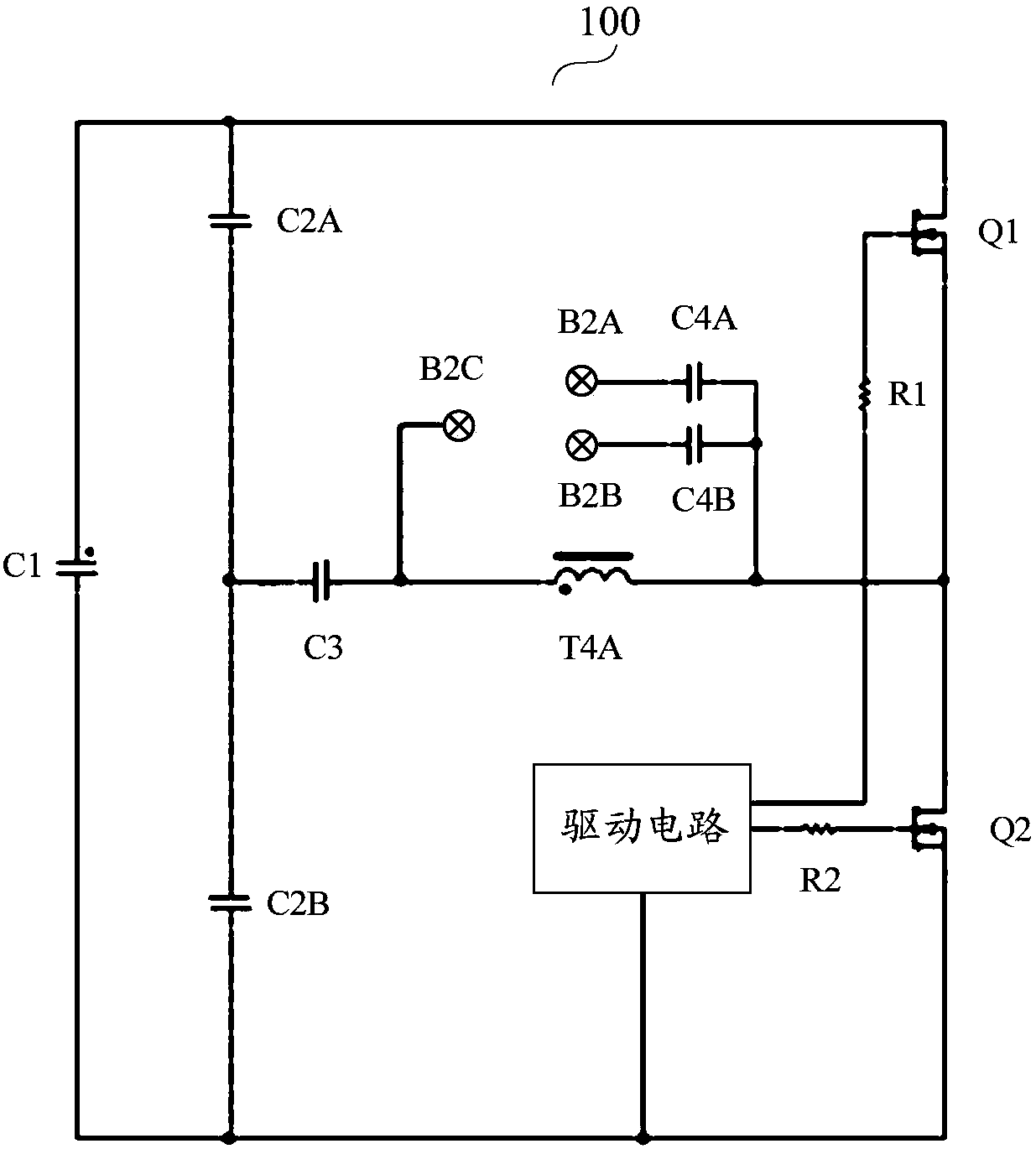
[0031] figure 1 It is a schematic structural block diagram of an LED driver in the prior art. like figure 1As shown, the LED driver 100 in the prior art may include a half-bridge circuit composed of a capacitor C2A, a capacitor C2B, a switch tube Q1 and a switch tube Q2, an electrolytic capacitor C1, current limiting resistors R1 and R2, a driving circuit, and a series resonance The capacitor C3 and the inductor T4A of the circuit, the LED load (not shown in the figure) and the current-limiting capacitors C4A and C4B connected in parallel to both ends of the inductor T4A. figure 1 The shown LED load includes two LED units. F...


PUM


Abstract

The invention discloses an LED driver and an LED lighting device. The LED driver comprises a bridge circuit, a parallel resonant circuit, an excitation source circuit and a starting circuit, wherein the bridge circuit comprises first to fourth bridge arms, a first node is arranged between the first bridge arm and the second bridge arm, a second node is arranged between the second bridge arm and the third bridge arm, a third node is arranged between the third bridge arm and the fourth bridge arm, a fourth node is arranged between the fourth bridge arm and the first bridge arm, DC voltage is inputted between the second node and the second node, the first bridge arm comprises a first transistor, the second bridge arm comprises a second transistor, and the first transistor and the second transistor are controlled to be conducted alternately; the parallel resonant circuit is coupled between the first node and the third node and comprises a resonant inductor and a resonant capacitor in parallel, and the parallel resonant circuit is suitable for driving an LED load; the excitation source circuit is suitable for providing excitation current for the parallel resonant circuit; and the starting circuit is suitable for controlling the second conductor to be conducted after the DC voltage is built to enable the parallel resonant circuit to start onset. The LED driver has an excellent load adjustment rate and high driving efficiency.

Description

technical field [0001] The invention relates to the field of light source driver design, in particular to an LED driver and an LED lighting device. Background technique [0002] In the field of lighting, fluorescent lamp is a traditional light source. It is a low-pressure gas discharge lamp, which exhibits negative resistance characteristics during operation. Most of them need a matching electronic ballast during operation. The LED light source has shown a wide range of application prospects due to its advantages of high light efficiency, long life and low cost. In more and more application scenarios, people prefer to replace traditional fluorescent lamps with LED light sources. [0003] In the prior art, when replacing a fluorescent lamp with an LED light source, in order not to dismantle the electronic ballast, an LED light source compatible with the electronic ballast can be directly selected, so that only the old fluorescent lamp needs to be simply removed and replaced ...

Claims


Application Information

Patent Timeline
Patent Type & Authority Applications(China)
IPC IPC(8): H05B33/08H05B44/00
CPCH05B45/00Y02B20/30
Inventor 陈忠王新胜陈亮邬秋峰
Owner SHANGHAI LUMIXESS TECH
Why Eureka
Try Eureka