Control circuit and control method of high-side depressurization converting circuit

A technology for converting circuits and controlling circuits, which is applied in the field of circuits, can solve problems such as differential load regulation, and achieve good load regulation effects

Active Publication Date: 2012-11-28
CHENGDU MONOLITHIC POWER SYST
View PDF4 Cites 10 Cited by
  • Summary
  • Abstract
  • Description
  • Claims
  • Application Information

AI Technical Summary

Problems solved by technology

[0016] The present invention proposes a solution to solve the

Method used


Image

  • Control circuit and control method of high-side depressurization converting circuit
  • Control circuit and control method of high-side depressurization converting circuit
  • Control circuit and control method of high-side depressurization converting circuit

Examples


Embodiment Construction

[0027] Specific embodiments of the present invention will be described in detail below in conjunction with the accompanying drawings.

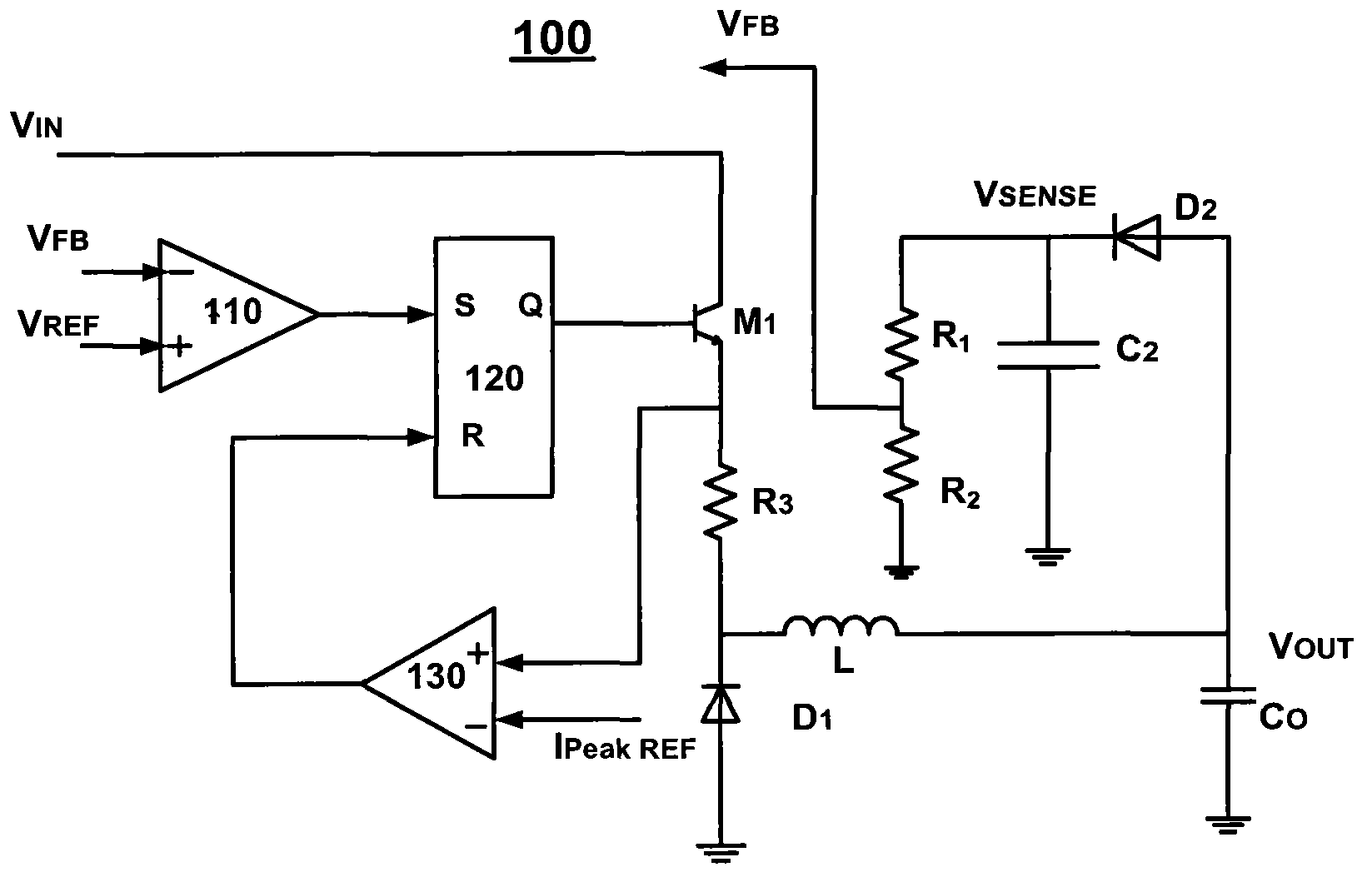
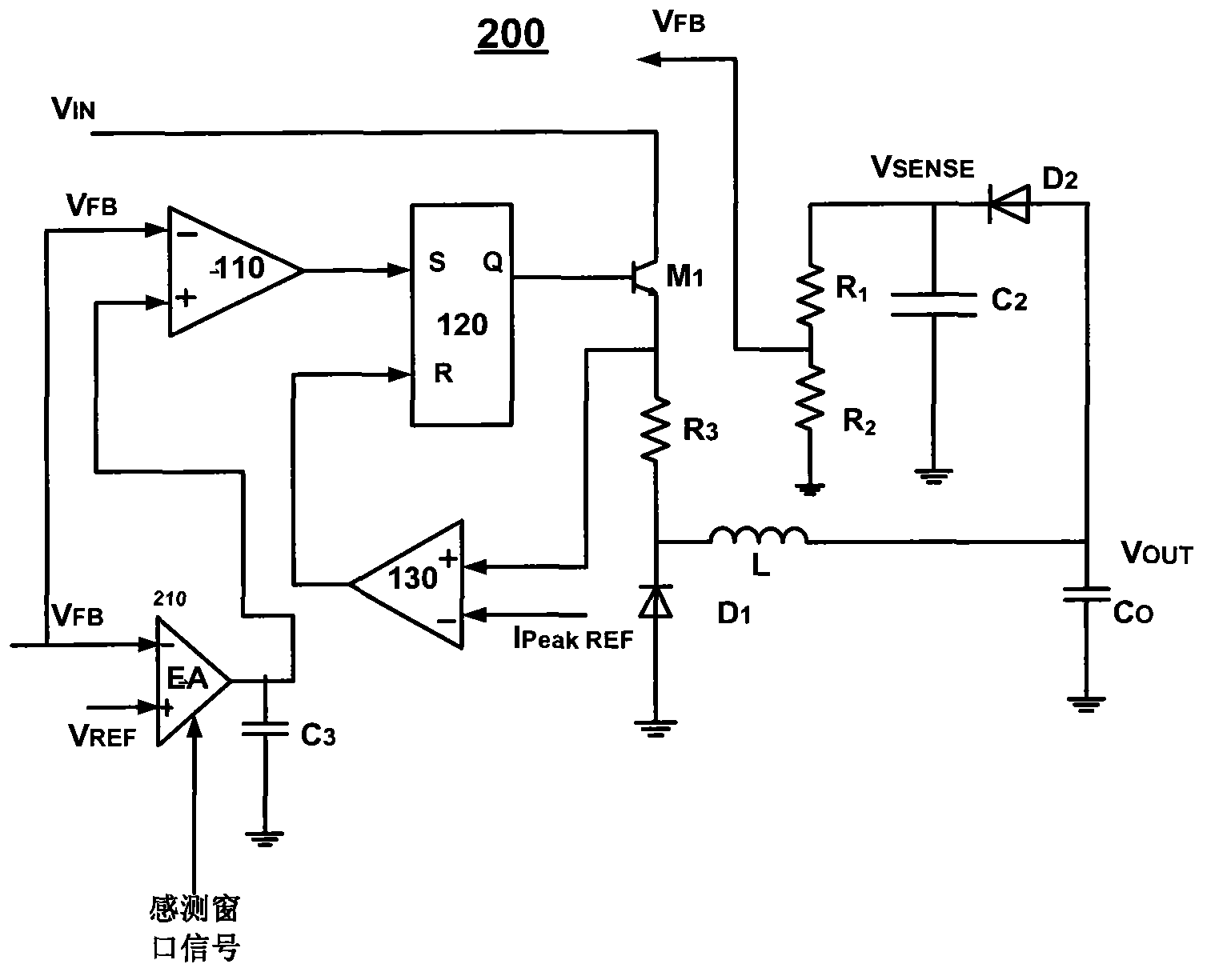
[0028] figure 2 A COT system 200 according to one embodiment of the invention is shown.

[0029] and figure 1 Compared to the COT system 100 shown in the figure 2 The COT system 200 shown adds a loop. More specifically, the COT system 200 includes an error amplifier 210 with a compensation capacitor C connected in parallel at its output 3 .

[0030] exist figure 2 In the illustrated embodiment, the error amplifier 210 is a transconductance amplifier. Of course, those skilled in the art should understand that other types of error amplifiers are also applicable in the present invention.

[0031] In system 200, the feedback signal V FB is input to the inverting input terminal of the error amplifier 210 and the inverting input terminal of the first comparator 110 . The non-inverting input terminal of the error amplifier 210 receives the r...


PUM


Abstract

The invention provides a control circuit of a high-side depressurization converting circuit. The control circuit comprises a sensor, a sensing window signal generator, an error amplifier, a first comparator, and a conduction time signal generator, wherein the sensor is used for sensing an output signal of the converting circuit so as to provide a sensing signal; the sensing window signal generator is used for generating a sensing window signal; the error amplifier is used for amplifying an error between a feedback signal and a reference signal of the sensing signal during a period of sensing a window, and outputting an error signal; the first comparator is used for comparing the error signal and the feedback signal and outputting a first comparison signal; and the conduction time signal generator is used for generating a conduction time signal according to the first comparison signal so as to control the conduction and the disconnection of upper and lower switching tubes of the converting circuit. According to the converting circuit provided by the invention, the control circuit can well regulate loads.

Description

technical field [0001] The invention relates to the field of circuits. More specifically, the present invention relates to a control circuit and a control method of a high-side buck converter circuit. Background technique [0002] In high-voltage step-down converter circuit (buck) applications, there are large voltage fluctuations at the switching nodes. Therefore, the buck control circuit needs to withstand high switching voltage and BST (bootstrap voltage), which makes it difficult to design the buck control circuit chip. In order to overcome this problem, the buck conversion circuit can be designed as a high-side buck conversion circuit by designing the reference ground of the buck control circuit as a switch node of the buck conversion circuit. [0003] However, such a high-side buck conversion circuit also has a defect, that is, the ground reference of the output of the high-side buck conversion circuit is different from the ground reference of the buck control circui...

Claims


Application Information

Patent Timeline
IPC IPC(8): H02M3/10
CPCG05F1/618H02M3/1563H02M1/0009H02M3/156
Inventor 李伊珂许力王锐
Owner CHENGDU MONOLITHIC POWER SYST
Why Eureka
Try Eureka