Electrolyte mixing tank and working method thereof

An electrolyte and mixing barrel technology, which can be used in mixer accessories, chemical instruments and methods, mixers with rotating mixing devices, etc., and can solve problems such as additive deposition.

Active Publication Date: 2021-01-05
丁建利
View PDF20 Cites 0 Cited by
  • Summary
  • Abstract
  • Description
  • Claims
  • Application Information

AI Technical Summary

Problems solved by technology

[0003] The purpose of the present invention is to provide an electrolyte mixing tank and its working method, which can solve the problem of additives being deposited on the bottom of the stirring shaft

Method used


Image

  • Electrolyte mixing tank and working method thereof
  • Electrolyte mixing tank and working method thereof
  • Electrolyte mixing tank and working method thereof

Examples


Embodiment 1

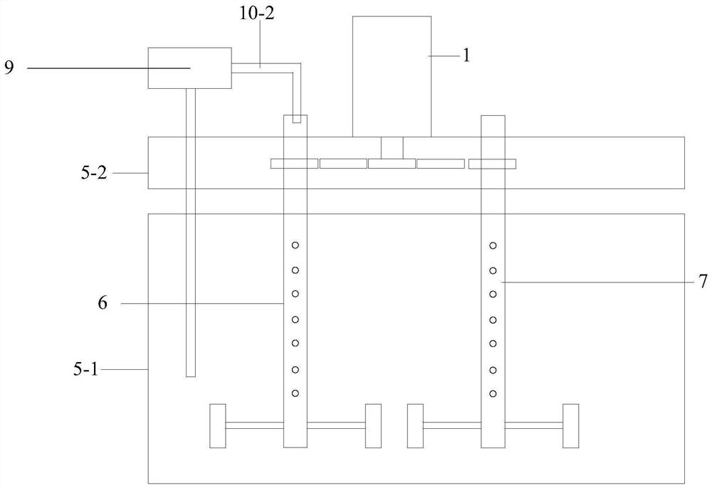
[0036] Embodiment one, such as Figure 1-5 As shown, the electrolyte mixing tank for producing copper foil includes: the tank body (5-1), the tank cover (5-2), and the first stirring shaft (6);

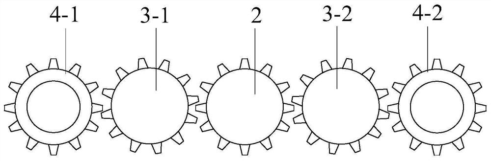
[0037] A driving motor (1) is fixed on the lid, and the rotating shaft of the driving motor is connected in sequence: a coupling, a reducer, and a driving gear (2). The driving gear meshes with the first transmission gear (3-1), and the first transmission The gear (3-1) meshes with the first driven gear (4-1); the driving gear (2), the first transmission gear (3-1), and the first driven gear (4-1) are arranged in the hollow inside the lid;

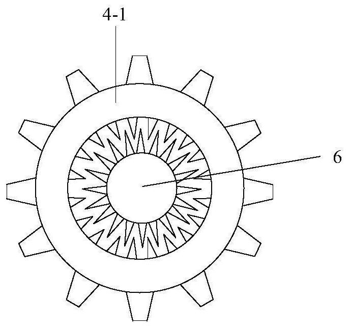
[0038] The inside of the first driven gear (4-1) is provided with a hollow hole; the first stirring shaft (6) is a hollow stirring shaft with both top and bottom ends open, which passes through the first driven gear (4-1) -1) is a hollow hole protruding from the barrel cover (5-2), the first stirring shaft (6) is fixedly connected with the first...

Embodiment 2

[0047] Embodiment two: if Image 6 As shown, the first stirring shaft (6) and the second stirring shaft (7) are " "shape, comprising: a first vertical part, a first horizontal part, a second vertical part, and stirring blades are arranged on the first vertical part and the second vertical part;

[0048] After the material of the circulation pipe and the material of the feed pipe flow into the mixing tank from the end of the second vertical part of the first stirring shaft and the second vertical part of the second stirring shaft and the through hole on the surface, due to the second stirring shaft of the first stirring shaft and the second stirring shaft The vertical part is constantly rotating in the mixing barrel, which makes the distribution of the solution in the barrel more uniform.

[0049] In addition, if Figure 7 As shown, the first vertical part and the second vertical part of the first stirring shaft (6) and the second stirring shaft (7) are provided with stirrin...

Embodiment 3

[0050] Embodiment three: as Figure 8 As shown, the electrolyte mixing tank needs to be cleaned regularly after being used for a period of time; at the same time, during the production process, the electrolyte mixing tank also needs to adjust its position frequently according to the actual production progress. The third embodiment is mainly as follows: the bottom of the electrolyte mixing tank is provided with rollers to meet the above two actual requirements. At the same time, while using rollers to facilitate the transportation of the electrolyte mixing tank, it also brings about a problem, how to fix the mixing tank (during normal construction, the mixing tank cannot be moved).

[0051] A support plate is provided at the bottom of the electrolyte mixing tank, and multiple rows of rollers are arranged on the underside of the support plate, wherein each row of rollers includes a plurality of rollers; a rolling shaft is fixedly connected between the rollers of each row of roll...


PUM


Abstract

The invention discloses an electrolyte stirring tank and a working method thereof; the main technical points are: the first stirring shaft is a hollow stirring shaft with openings at both top and bottom ends, and the first stirring shaft (6) includes: a first vertical part , the first horizontal part, the second vertical part, stirring blades are all set on the first vertical part and the second vertical part, and the first vertical part and the second vertical part of the first stirring shaft are all provided with stirring blades , and the area of ​​the stirring blade of the second vertical portion is wider than the stirring area of ​​the stirring blade of the first vertical portion; The problem with the bottom of the axis.

Description

technical field [0001] The present invention relates to the technical field of stirring mechanism, and more specifically, relates to an electrolyte stirring tank and a working method thereof. Background technique [0002] It is recorded in CN205856623U that in the production process of copper electrolysis, additives such as glue or surface active substances need to be added to the electrolytic solution. dead space directly below the shaft, causing additives to deposit there" technical problem. Contents of the invention [0003] The object of the present invention is to provide an electrolyte stirring tank and its working method, which can solve the problem of additives being deposited on the bottom of the stirring shaft. [0004] The technical solution of the present invention is realized in the following way: an electrolyte stirring tank, comprising: a tank body (5-1), a tank cover (5-2), and a first stirring shaft (6); [0005] A driving motor (1) is fixed on the lid, ...

Claims


Application Information

Patent Timeline
Patent Type & Authority Patents(China)
IPC IPC(8): B01F7/18B01F15/00B01F15/02B01F15/06B01F7/00
CPCB01F27/211B01F27/2122B01F27/2322B01F27/90B01F35/45B01F35/7176B01F35/90B01F2035/99
Inventor 杨照辉周义勇刘知凡郑书强
Owner 丁建利
Why Eureka
Try Eureka