An electrolyte feeding device
A technology of feeding device and electrolyte, applied in electrolysis components, electrolysis process, instruments, etc., can solve the problems of "additive deposition in this place", dead angle of stirring shaft, etc.
- Summary
- Abstract
- Description
- Claims
- Application Information
AI Technical Summary
Problems solved by technology
Method used
Image
Examples
Embodiment 1
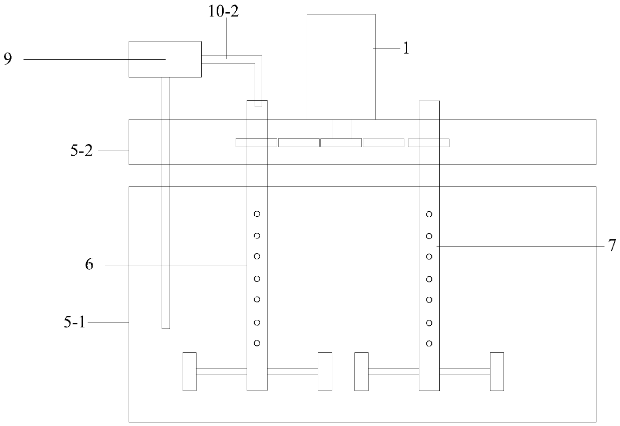
[0034] Embodiment one, such as Figure 1-5 As shown, the electrolyte mixing tank for producing copper foil includes: the tank body (5-1), the tank cover (5-2), and the first stirring shaft (6);
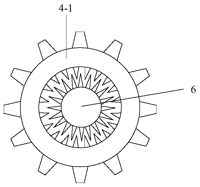
[0035] A driving motor (1) is fixed on the lid, and the rotating shaft of the driving motor is connected in sequence: a coupling, a reducer, and a driving gear (2). The driving gear meshes with the first transmission gear (3-1), and the first transmission The gear (3-1) meshes with the first driven gear (4-1); the driving gear (2), the first transmission gear (3-1), and the first driven gear (4-1) are arranged in the hollow inside the lid;
[0036] The inside of the first driven gear (4-1) is provided with a hollow hole; the first stirring shaft (6) is a hollow stirring shaft with both top and bottom ends open, which passes through the first driven gear (4-1) -1) is a hollow hole protruding from the barrel cover (5-2), the first stirring shaft (6) is fixedly connected with the first...
Embodiment 2
[0045] Embodiment two: if Figure 6 As shown, the first stirring shaft (6) and the second stirring shaft (7) are " "shape, comprising: a first vertical part, a first horizontal part, a second vertical part, and stirring blades are arranged on the first vertical part and the second vertical part;
[0046] After the material of the circulation pipe and the material of the feed pipe flow into the mixing tank from the end of the second vertical part of the first stirring shaft and the second vertical part of the second stirring shaft and the through hole on the surface, due to the second stirring shaft of the first stirring shaft and the second stirring shaft The vertical part is constantly rotating in the mixing barrel, which makes the distribution of the solution in the barrel more uniform.
[0047] In addition, if Figure 7 As shown, the first vertical part and the second vertical part of the first stirring shaft (6) and the second stirring shaft (7) are provided with stirri...
Embodiment 3
[0048] Embodiment three: as Figure 8 As shown, the electrolyte mixing tank needs to be cleaned regularly after being used for a period of time; at the same time, during the production process, the electrolyte mixing tank also needs to adjust its position frequently according to the actual production progress. The third embodiment is mainly as follows: the bottom of the electrolyte mixing tank is provided with rollers to meet the above two actual needs. At the same time, while using rollers to facilitate the transportation of the electrolyte mixing tank, it also brings about a problem, how to fix the mixing tank (during normal construction, the mixing tank cannot be moved).
[0049] A support plate is provided at the bottom of the electrolyte mixing tank, and multiple rows of rollers are arranged on the underside of the support plate, wherein each row of rollers includes a plurality of rollers; a rolling shaft is fixedly connected between the rollers of each row of rollers, an...
PUM
 Abstract
Description
Claims
Application Information
 - R&D
- Intellectual Property
- Life Sciences
- Materials
- Tech Scout
- Unparalleled Data Quality
- Higher Quality Content
- 60% Fewer Hallucinations
Browse by: Latest US Patents, China's latest patents, Technical Efficacy Thesaurus, Application Domain, Technology Topic, Popular Technical Reports.
© 2025 PatSnap. All rights reserved.Legal|Privacy policy|Modern Slavery Act Transparency Statement|Sitemap|About US| Contact US: help@patsnap.com


