Control method of cooling system and vehicle

A technology of a cooling system and a control method, which is applied in the control of coolant flow, liquid cooling, engine cooling, etc., can solve the problem that the temperature of oil and cylinder liner cannot be effectively increased, the heat cannot be effectively used, and the friction loss of the engine It can improve the lifting speed and heating response, avoid heat transfer, and reduce premature ignition and knocking.

Active Publication Date: 2018-07-10
GREAT WALL MOTOR CO LTD
View PDF6 Cites 3 Cited by
  • Summary
  • Abstract
  • Description
  • Claims
  • Application Information

AI Technical Summary

Problems solved by technology

[0003] In related technologies, most of the cooling systems of engines use thermostats for water temperature control. Because thermostats cannot effectively manage the heat of the engine, for example, when the engine is cold started, the heat generated by the engine cannot be effectively used to rapidly increase combustion. chamber wall temperature, resulting in abnormal combustion state, thereby increasing fuel consumption and emissions
In addition, since the temperature of the engine oil and the cylinder liner cannot be effectively increased in a short period of time, the frictional work loss of the engine at the initial stage of starting is high, the oil is diluted seriously, and the fuel consumption is increased.
In the full load stage after the heat engine is completed, due to the high water temperature, it leads to the occurrence of early ignition and knocking
At the same time, due to the failure of effective use of heat, the temperature of the engine water rises slowly, which affects the comfort of the ride.

Method used


Image

  • Control method of cooling system and vehicle
  • Control method of cooling system and vehicle
  • Control method of cooling system and vehicle

Examples


Embodiment Construction

[0029] It should be noted that, in the case of no conflict, the embodiments of the present invention and the features in the embodiments can be combined with each other.

[0030] The present invention will be described in detail below with reference to the accompanying drawings and examples.

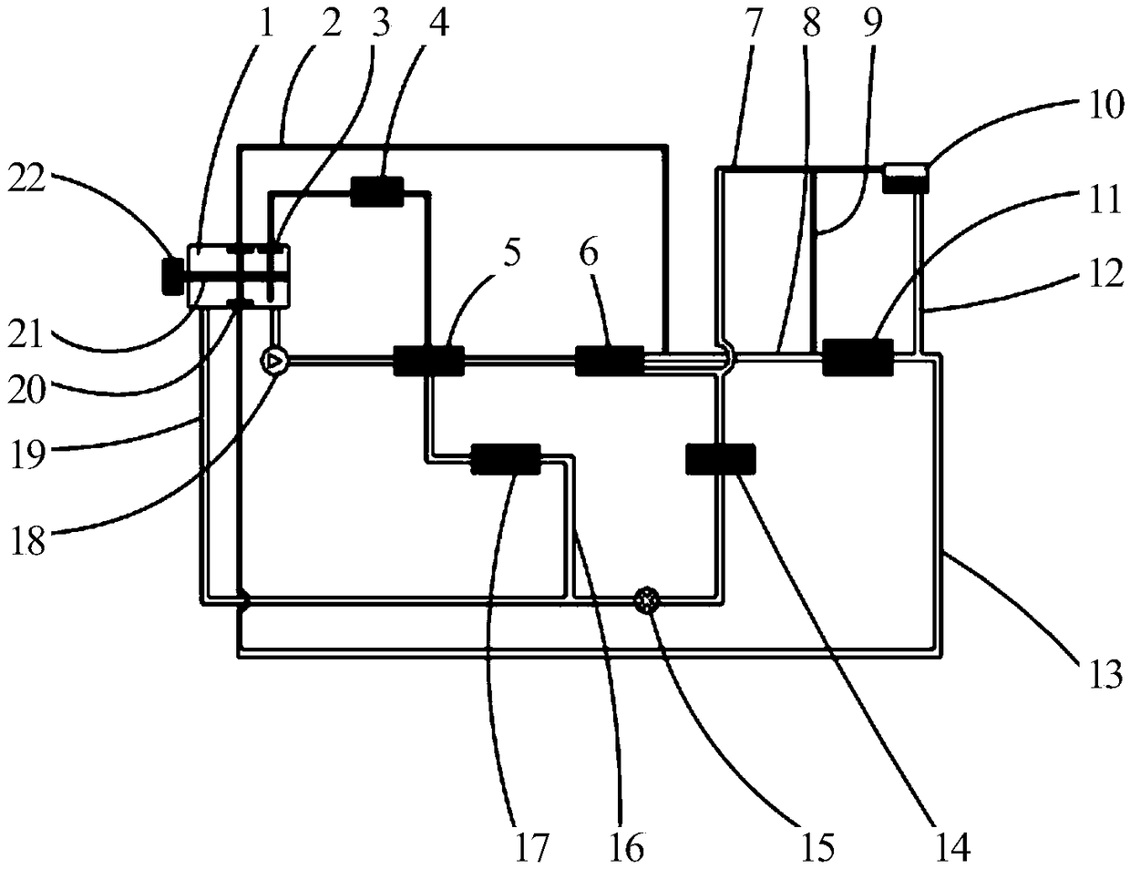
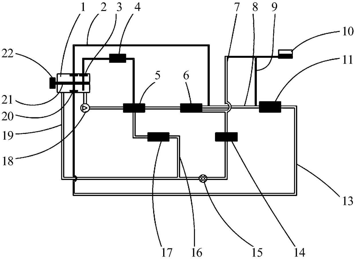
[0031] figure 1 is a schematic diagram of a cooling system according to one embodiment of the invention.

[0032] Such as figure 1 As shown, the cooling system according to one embodiment of the present invention includes: coolant flow distribution device 1 (abbreviated as coolant distribution device 1), oil cooler 4, cylinder block water jacket 5, cylinder head water jacket 6, radiator 11 and warm air core body 14.

[0033] Among them, the water pump 18 is connected with the coolant flow distribution device 1; the coolant flows from the coolant flow distribution device 1 through the water pump 18, the cylinder water jacket 5 and the cylinder head water jacket 6 in turn, and then retu...


PUM


Abstract

The invention provides a control method of a cooling system and a vehicle. The control method of the cooling system comprises the steps that S1, the water temperature of an engine is determined; and S2, flow distribution of coolants in a bypass loop, a large circulation loop and an engine oil cooler loop is controlled according to the water temperature of the engine. According to the control method of the cooling system, oil consumption can be effectively reduced, emissions can be reduced, and taking comfort can be improved.

Description

technical field [0001] The invention relates to the technical field of automobiles, in particular to a cooling system control method and a vehicle. Background technique [0002] With the continuous aggravation of the energy crisis and the continuous deterioration of the environment, vehicle emission regulations are becoming more and more stringent. In addition, with the continuous improvement of people's material living standards, people's requirements for vehicle driving comfort are also constantly increasing, which requires auto manufacturers to better resolve the contradiction between vehicle fuel economy, emissions and driving comfort. The fuel economy and riding comfort of the car can be improved through thermal management of the engine. [0003] In related technologies, most of the cooling systems of engines use thermostats for water temperature control. Because thermostats cannot effectively manage the heat of the engine, for example, when the engine is cold started,...

Claims


Application Information

Patent Timeline
Patent Type & Authority Applications(China)
IPC IPC(8): F01P7/16F01P11/16F01P3/02F01P5/10F01P3/04F01P11/08
CPCF01P3/02F01P3/04F01P5/10F01P7/165F01P11/08F01P11/16F01P2003/028F01P2050/22F01P2060/04
Inventor 王凯凯夏朝辉闫立虎萨如拉曹永伟徐天博崔鹏程
Owner GREAT WALL MOTOR CO LTD
Why Eureka
Try Eureka