
Control method and controller

A controller and pulse width modulation technology, used in the control of electromechanical brakes, current controllers, control systems, etc., can solve the problems of increasing difficulty in motor control and being easily limited by working conditions, and achieve precise control and high estimation accuracy. Effect

Active Publication Date: 2020-09-01
GREAT WALL MOTOR CO LTD
View PDF6 Cites 4 Cited by
  • Summary
  • Abstract
  • Description
  • Claims
  • Application Information

AI Technical Summary

Problems solved by technology

[0004] The present invention proposes a control method to solve the problem that the existing bus current estimation control method is easily limited by working conditions, resulting in increased difficulty in controlling the motor

Method used


Image

  • Control method and controller
  • Control method and controller
  • Control method and controller

Examples


Embodiment Construction

[0065] It should be noted that, in the case of no conflict, the embodiments of the present invention and the features in the embodiments can be combined with each other.

[0066] The present invention will be described in detail below with reference to the accompanying drawings and examples.

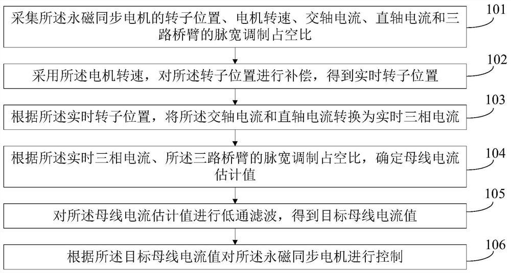
[0067] figure 1 It shows one of the flowcharts of the control method described in the embodiment of the present invention, the method may include:

[0068] Step 101 , collecting the rotor position, motor speed, quadrature axis current, direct axis current and pulse width modulation duty cycle of the three-way bridge arm of the permanent magnet synchronous motor.

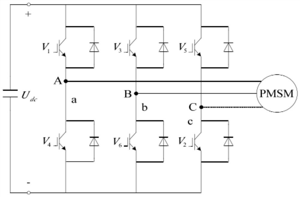
[0069] In the embodiment of the present invention, the permanent magnet synchronous motor is a synchronous motor that is excited by a permanent magnet to generate a synchronous rotating magnetic field. The permanent magnet acts as a rotor to generate a rotating magnetic field. The three-phase stator winding reacts through the ...


PUM


Abstract

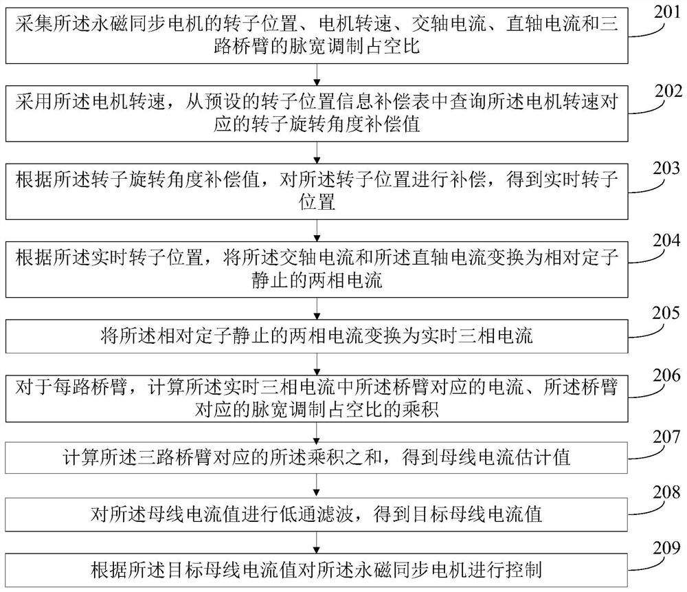
The invention provides a control method and a controller. The method comprises the following steps of collecting a rotor position, a motor rotating speed, a quadrature-axis current, a direct-axis current of a permanent magnet synchronous motor and the pulse width modulation duty ratios of three bridge arms; compensating the rotor position according to the rotating speed of the motor; and calculating a three-phase current according to the compensated rotor position information, finally determining a bus current estimation value by using the three-phase current and a PWM value as the calculationinput of the bus current, and performing low-pass filtering on the bus current estimation value to obtain a target bus current value, thereby controlling the permanent magnet synchronous motor according to the target bus current value. According to the control method provided by the invention, the three-phase current can be compensated at any position, and in all working conditions, no matter whether the rotating speed of the motor is high or low, the estimation precision is higher, so that the engineering personnel can master the bus current at any time, and furthermore, the precise controlon the permanent magnet synchronous motor is realized.

Description

technical field [0001] The invention relates to the technical field of motors, in particular to a control method and a controller. Background technique [0002] In recent years, clean energy vehicles have attracted more and more attention. Among them, the power of pure electric vehicles mainly comes from motors, and permanent magnet synchronous motors are widely used due to their high power density and high efficiency. For permanent magnet synchronous motor drive controllers, the bus current is required to monitor the state of the current controller, so it is necessary to obtain the bus current of the current controller. [0003] Using software to estimate the bus current can save costs and improve system reliability. At present, the method of estimating the bus current by software is: within a switching period T, use the adjustment coefficient λ to adjust the action time ta, tb, tc of the three-phase current ia, ib, ic in the bus, and get ta1=λta( (k-1)T)+(1-λ)ta(kT); tb1...

Claims


Application Information

Patent Timeline
Patent Type & Authority Applications(China)
IPC IPC(8): H02P6/28H02P21/18H02P21/22H02P27/12
CPCH02P6/28H02P21/18H02P21/22H02P27/12H02P21/0025
Inventor 王倩男阿勒普·加纳
Owner GREAT WALL MOTOR CO LTD
Learn More