Power amplifier for real-time simulation of power system

A power amplifier and real-time simulation technology, applied in the output power conversion device, the conversion of AC power input to AC power output, the conversion of AC power input to DC power output, etc., can solve the problem of increasing heat flow through power and reducing power usage. , short delay and other issues, to achieve the effect of improving the output power level, meeting real-time simulation, and improving the power level

Active Publication Date: 2018-07-31
CHINA ELECTRIC POWER RES INST +1
View PDF5 Cites 3 Cited by
  • Summary
  • Abstract
  • Description
  • Claims
  • Application Information

AI Technical Summary

Problems solved by technology

[0004] At present, in order to meet the requirements of real-time changes and high-frequency harmonics, the products on the market all use linear power semiconductor devices to build topology structures. The advantages of linear power semiconductor devices are that the output of strong electric voltage can follow the change of weak electric The frequency range is wide and there is no harmonic interference; however, due to the technical level limitation of linear power semiconductor devices and the fact that they work in the linear working area of ​​semiconductor devices, the semiconductor itself generates serious heat, and the heat generation is proportional to the increase in the power flowing through. Therefore, the power level of power amplifiers using linear power semiconductor devices cannot be very high
On the other hand, the main circuit of the power amplifier using linear power devices is a simple amplifying circuit, which cannot realize the control algorithm of power feedback to the grid, and when the power amplifier is externally connected to power generation equipment, the power input to the power amplifier can only rely on internal energy consumption Resistor consumption, and the resistance of the internal energy-dissipating resistor is limited by the size and heat of the resistor and cannot be done very much, and the power usage needs to be reduced, thus limiting the use of power amplifiers

Method used


Image

  • Power amplifier for real-time simulation of power system
  • Power amplifier for real-time simulation of power system
  • Power amplifier for real-time simulation of power system

Examples


Embodiment

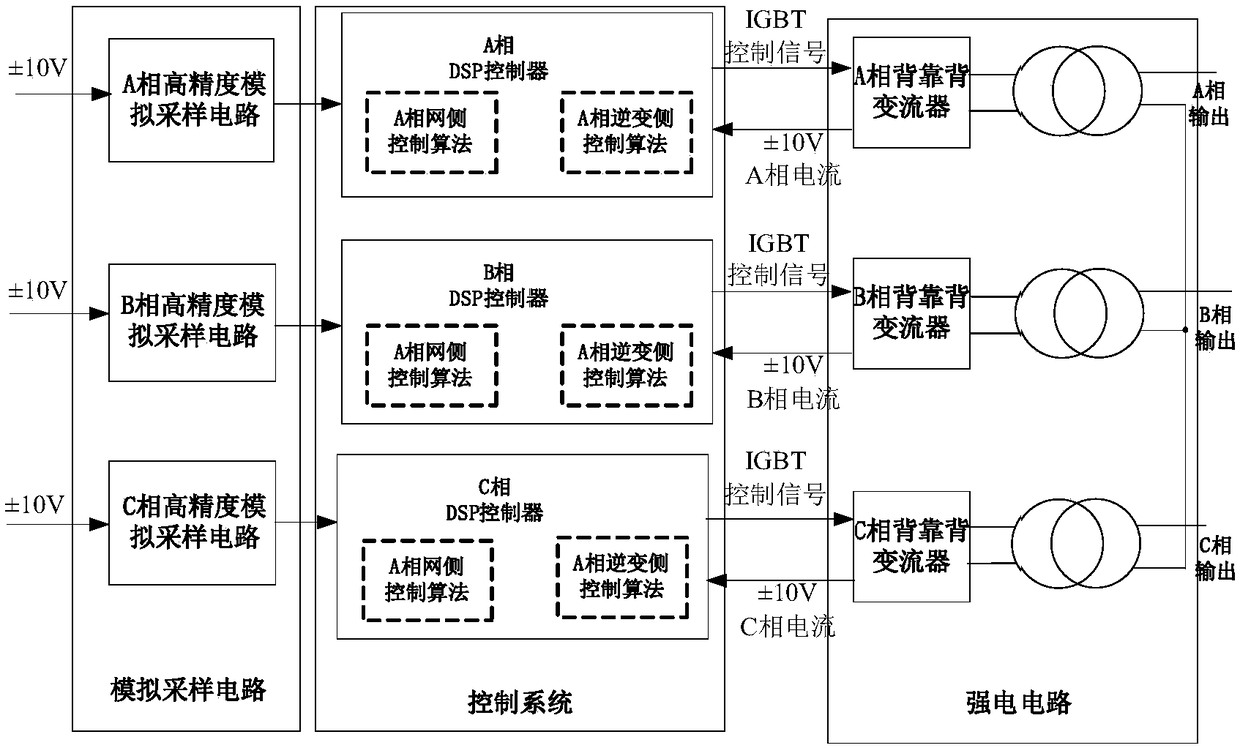
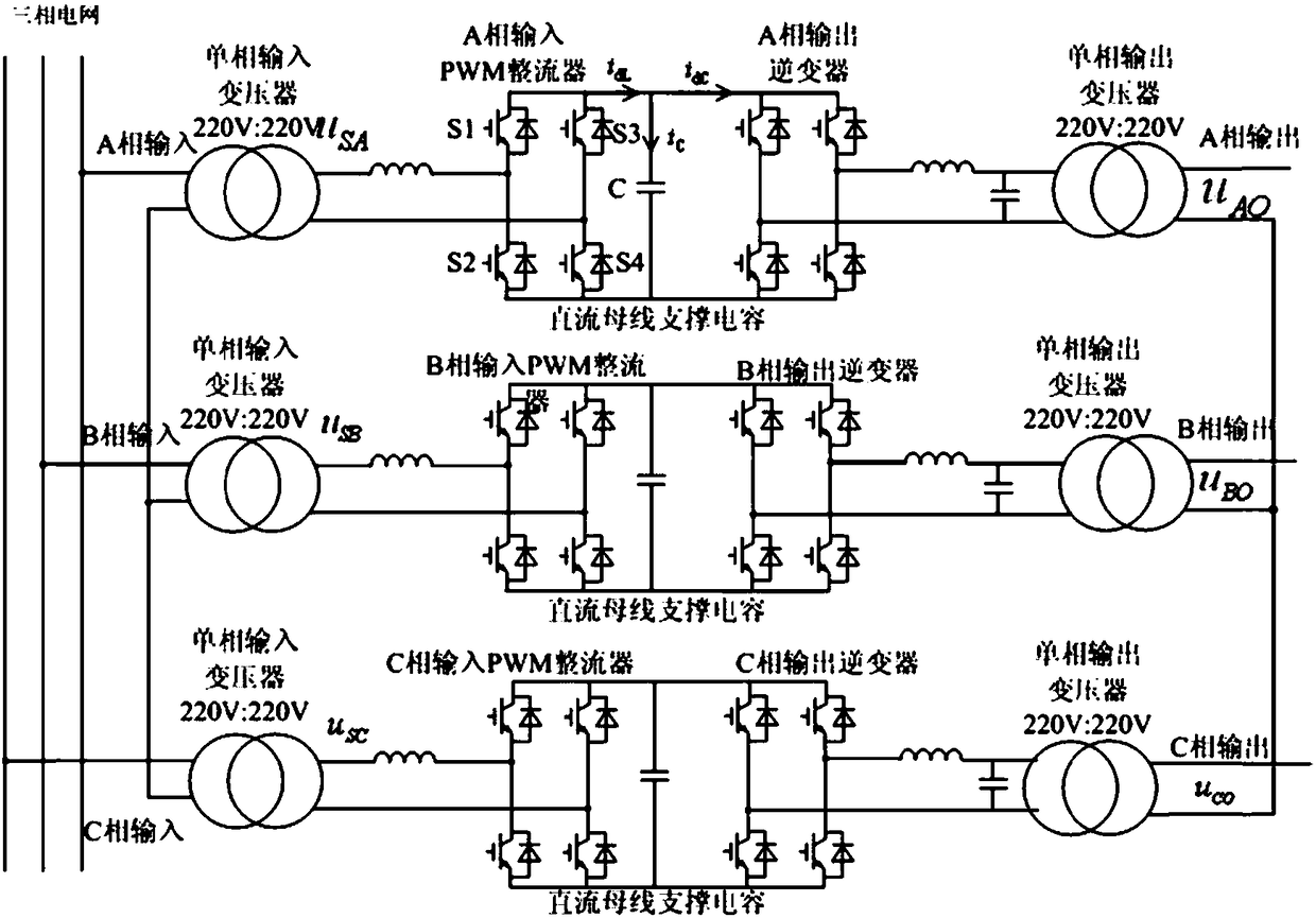
[0059] Such as figure 1 As shown, the present invention includes three parts: an analog sampling circuit, a control system, and a strong current circuit. Such as figure 2 As shown, this product requires 6 single-phase isolation transformers of 220V:220V, 3 sets on the input side and 3 sets on the output side. One end of the three single-phase transformers on the input side is connected to phase A, B, and C of the power grid by wires, and the other end is connected by wires; one end of the three single-phase transformers on the output side is connected by wires, and the other One end is used as the A-phase, B-phase, and C-phase output of the power amplifier; in addition, the high-current part of the present invention requires 24 IGBTs to form 3 single-phase back-to-back converters;

[0060] The analog sampling circuit and the control system are the weak current parts of the present invention. The analog sampling circuit needs ADC chip to realize, the generation of PWM wave needs...


PUM


Abstract

The invention provides a power amplifier for real-time simulation of a power system. The power amplifier comprises three phases of independently-operating amplification circuits, each amplification circuit comprises a high-precision analog sampling circuit, a control system and a strong current circuit which are connected in sequence; the control system comprises a DSP controller; the strong current circuit comprises a back-to-back converter; and the power amplifier outputs load through a three-phase star structure formed by connection of single-phase output transformers in the back-to-back converter. The technical scheme provided in the invention greatly improves the output power grade and reduces the heating amount of the device.

Description

Technical field [0001] The present invention belongs to the field of real-time simulation of electric power system. Specifically, the present invention provides a power amplifier for real-time simulation of electric power system. Background technique [0002] Power amplifier (English name: power amplifier), referred to as "power amplifier", refers to an amplifier that can generate the maximum power output to drive a certain load under a given distortion rate. [0003] As the core equipment of power system power-in-loop simulation, the main function of the power amplifier is that the output strong current voltage changes in real time with the input weak current signal, and the power system simulation needs to simulate the normal and faulty working conditions of the power system. Therefore, the power amplifier also To have high-frequency harmonic injection, low-frequency harmonic disturbance, unbalanced voltage output and other functions, as well as a higher power level, puts high te...

Claims


Application Information

Patent Timeline
Patent Type & Authority Applications(China)
IPC IPC(8): H02M5/458H02M7/219H02M7/5387
CPCH02M5/458H02M7/219H02M7/53873H02M7/53875
Inventor 李洋石文辉张兴高松罗魁
Owner CHINA ELECTRIC POWER RES INST
Why Eureka
Try Eureka