Dual-plate-type die closing unit used for moulding machine

A molding machine and molding die technology, applied in the field of double-plate clamping unit, can solve the problems of increasing the structural length of the clamping unit and the limited change in length, etc.

Active Publication Date: 2018-08-07
ENGEL AUSTRIA
View PDF4 Cites 2 Cited by
  • Summary
  • Abstract
  • Description
  • Claims
  • Application Information

AI Technical Summary

Problems solved by technology

The following disadvantage arises here: Although magnetostrictive materials can achieve high force densities, the change in length per unit length is strongly limited
Because the split nut used for locking cannot be locked in any position of the tie rods (in practice, the groove of the outer profile on the at least one tie rod can be several centimeters wide), so a very long Main body made of magnetostrictive material, thereby increasing the overall structural length of the clamping unit
This is already a disadvantage in itself and is magnified by having to use large quantities of relatively expensive magnetostrictive material

Method used


Image

  • Dual-plate-type die closing unit used for moulding machine
  • Dual-plate-type die closing unit used for moulding machine
  • Dual-plate-type die closing unit used for moulding machine

Examples


Embodiment Construction

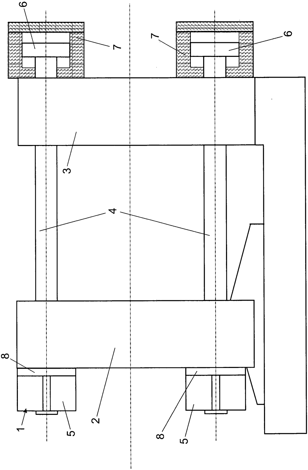
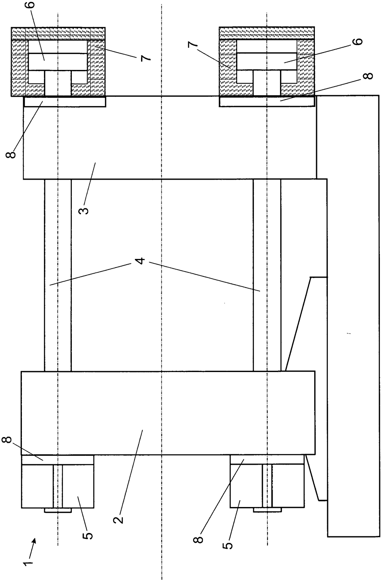
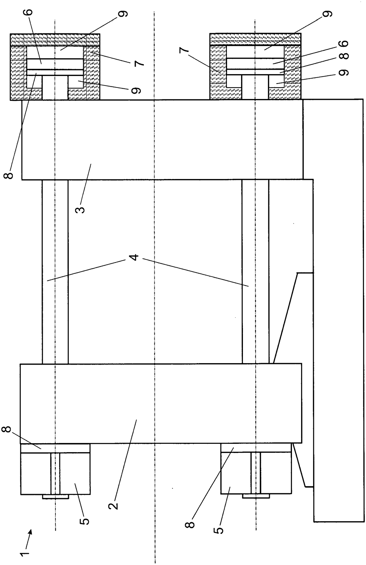
[0033] exist figure 1 The molding machine (in this case an injection molding machine) according to the invention shown in has a movable first mold clamping plate 2 and a fixed second mold clamping plate in the region of the double-platen clamping unit 1 3. Two mold clamping plates 2 and 3 are penetrated by four tie rods 4 . The tie rod 4 is mounted movably both relative to the first mold clamping plate 2 and also relative to the second mold clamping plate 3 .

[0034] Each locking device 5 is used for locking the pull rod 4 and the first mold clamping plate 2 . The locking devices 5 are each configured as split nuts. The inner contour of the split nut cooperates with the outer contour on the rod 4 in the closed state of the nut, thereby realizing the locking of the rod 4 and the first mold clamping plate 2 .

[0035] Piston-cylinder units 6 , 7 are arranged on the side of the second mold clamping plate 3 facing away from the first mold clamping plate 2 . The cylinders 7 o...


PUM


Abstract

The invention relates to a dual-plate-type die closing unit used for a moulding machine, which is used for applying a die closing force to at least two moulding mold parts and includes: a first and asecond mold clamping boards which can move relative to each other; a pull rod which penestrates through the first and a second mold clamping boards and moves relative to the same; a locking apparatus,by which the pull rod can be locked with the first mold clamping board and / or a piston-cylinder unit; the piston-cylinder unit which is configured to apply at least one part of a die closing force asa part of a die closing force apparatus and / or enable the pull rod to move relative to the first and / or second mold clamping boards as a part of a mold height adjustment apparatus, wherein the die closing force apparatus includes an active material configured to apply a part of the die closing force under effect of electromagnetic field and / or temperature varying, and / or, the mold height adjustment apparatus includes the active material, which is configured to determine extension size of defining the mold height of the active material under the effect of the electromagnetic field and / or temperature varying.

Description

technical field [0001] The invention relates to a two-platen clamping unit for a forming machine, which has the features stated in the preamble of claim 1 . Background technique [0002] A molding machine is understood here to mean an injection molding machine, a die-casting machine, a pressing machine and the like. [0003] Prior art injection molding machines of this type have a first mold clamping plate (for example movable relative to the machine frame) on which a part of the forming mold (usually a mold half) can be mounted . Likewise, a second mold clamping plate (fixed relative to the frame) is provided, on which another part of the forming mold can be mounted. The two mold clamping plates are penetrated by at least one tie rod, wherein in practice the embodiment with four tie rods penetrating the mold clamping plates is the most common. [0004] The at least one tie rod can be locked relative to the first mold clamping plate by means of a locking device. That end...

Claims


Application Information

Patent Timeline
Patent Type & Authority Applications(China)
IPC IPC(8): B29C45/67
CPCB29C45/6728B29C2045/645B29C2045/647B29C45/67
Inventor G·肖特H·蔡德尔霍费尔
Owner ENGEL AUSTRIA
Why Eureka
Try Eureka