Segmented electrical machine

a technology of electrical machines and segments, applied in the direction of machines/engines, magnetic circuit rotating parts, magnetic circuit shapes/forms/construction, etc., can solve the problems of reducing bearing life, severe deformation, and radial unbalanced magnetic force (umf) on the variable reluctance rotor, so as to reduce the space requirement of the balancing segment

Active Publication Date: 2019-03-14
ROLLS ROYCE PLC
View PDF0 Cites 1 Cited by
  • Summary
  • Abstract
  • Description
  • Claims
  • Application Information

AI Technical Summary

Benefits of technology

[0023]The core structure of the, or each, balancing segment may be an E-core structure or a U-core structure. In the case of a U-core structure, the conductor winding may have a thinner layer of conductors on a side of the winding distal from the rotor than on a side of the winding proximal the rotor. This can help to reduce the space requirement of the balancing segment.

Problems solved by technology

However, because the stator segments are non-axisymmetrically distributed, they exert a radial unbalanced magnetic force (UMF) on the variable reluctance rotor when the machine is operated as a motor.
As a consequence, increased shaft eccentricities and bearing friction can considerably decrease bearing life.
Moreover, the UMF can serve as external excitation source for rotor vibrations such that, when close to system resonant frequencies, severe deformation can occur.
the stator segments are arranged in the array such that, when energized to rotate the rotor, they produce an unbalanced force on the rotor; and
Examples of applications of the electrical machine include: embedded starter / generators, engine fuel pumps and hybrid propulsion systems in which the unevenness of available space as well as the low accessibilities of embedding locations pose challenges to conventional annular stator electrical machines.

Method used


Image

  • Segmented electrical machine
  • Segmented electrical machine
  • Segmented electrical machine

Examples


Embodiment Construction

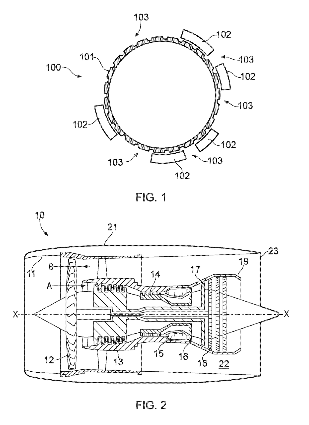
[0042]With reference to FIG. 2, a ducted fan gas turbine engine is generally indicated at 10 and has a principal and rotational axis X-X. The engine comprises, in axial flow series, an air intake 11, a propulsive fan 12, an intermediate pressure compressor 13, a high-pressure compressor 14, combustion equipment 15, a high-pressure turbine 16, an intermediate pressure turbine 17, a low-pressure turbine 18 and a core engine exhaust nozzle 19. A nacelle 21 generally surrounds the engine 10 and defines the intake 11, a bypass duct 22 and a bypass exhaust nozzle 23.

[0043]During operation, air entering the intake 11 is accelerated by the fan 12 to produce two air flows: a first air flow A into the intermediate-pressure compressor 13 and a second air flow B which passes through the bypass duct 22 to provide propulsive thrust. The intermediate-pressure compressor 13 compresses the air flow A directed into it before delivering that air to the high-pressure compressor 14 where further compres...


PUM


Abstract

An electrical machine has a variable reluctance rotor, and a stator formed as an annular array of stator segments. The reluctance of the rotor-to-stator magnetic flux path varies with rotor position whereby the stator segments are magnetically energizable to rotate the rotor. The stator segments are arranged in the array such that, when energized to rotate the rotor, they produce an unbalanced force on the rotor. The machine further has a compensator including one or more balancing segments which are configured to be magnetically energizable to produce a balancing force on the rotor which balances the unbalanced force. The reluctance of the rotor-to-compensator magnetic flux path is substantially invariant with rotor position.

Description

CROSS-REFERENCE TO RELATED APPLICATIONS[0001]This application is based upon and claims the benefit of priority from British Patent Application No. GB 1714785.1, filed on 14 Sep. 2017, the entire contents of which are herein incorporated by reference.BACKGROUNDTechnical Field[0002]The present disclosure relates to a segmented electrical machine. In particular, but not exclusively, it relates to a segmented electrical machine to be mounted in a gas turbine engine or other rotating assembly.[0003]Description of the Related Art EP A 3035504 proposes an electrical machine having a variable reluctance rotor and an annular array of stator segments which are each configured to function, in conjunction with the rotor, as an electrical machine. Advantageously, the variable reluctance rotor can be integrated with or mounted to the radial periphery of a rotor stage, or a pair of axially spaced rotor stages, of a gas turbine engine, whereby the weight of the machine and the number of its compone...

Claims


Application Information

Patent Timeline
Patent Type & Authority Applications(United States)
IPC IPC(8): H02K7/04H02K1/24H02K11/30H02K7/18F01D15/00
CPCH02K7/04H02K1/246H02K11/30H02K7/1823F01D15/00F05D2220/768F02C7/268F02C7/32F01D5/027F01D15/10F05D2220/323F05D2260/96H02K1/148H02K7/09H02K19/103H02K41/03H02K2201/15H02K2213/12
Inventor CHONG, ELLIS FHRAMAKRISHNA, SHANMUKHAVISWANATHAN, VAIYAPURIWANG, SHUAI
Owner ROLLS ROYCE PLC
Why Eureka
Try Eureka