Twin-clutch transmission

a transmission and twin-clutch technology, applied in mechanical actuated clutches, brake systems, gearing, etc., can solve the problems of inability to achieve satisfactory acceleration performance and fuel economy, automobile cannot be reliably parked on a sloping road, and cannot achieve reliable stopping.

Inactive Publication Date: 2008-03-11
KYOWA METAL WORKS
View PDF17 Cites 75 Cited by
  • Summary
  • Abstract
  • Description
  • Claims
  • Application Information

AI Technical Summary

Benefits of technology

[0011]The pair of first speed gears and the first speed sleeve are provided between the pair of third speed gears and the pair of fifth speed gears, the 3-5 speed sleeve and the pair of first speed gears partially overlap in an axial direction, and recesses are formed in the first speed output gear, second speed output gear, and backward output gear each of which has a large diameter so that the respective sleeves can go into the recesses when they stroke, and as a result, the total length of the transmission can be reduced.
[0014]Since the third speed input gear of the pair of third speed gears, which is integrated with the first input shaft, doubles as the backward input gear, manufacturing costs can be reduced due to a decrease in the number of parts, and the total length of the transmission can be reduced because of a decrease in the space required.
[0017]The axial space required for backward driving can be small, and the total length of the transmission can be reduced.
[0020]The axial space required for the pair of third speed gears, the pair of fifth speed gears, and the pair of first speed gears and the sleeves for connecting them can be small, and hence the total length of the transmission can be reduced.
[0023]In the seven forward speed transmission, manufacturing costs can be reduced due to a decrease in the number of parts, and the total length of the transmission can be reduced since the space required can be small.
[0025]By mechanically locking the teeth formed on the sleeve, the first output shaft or the second output shaft is locked in the rotative direction, and therefore the automobile can be reliably stopped.

Problems solved by technology

However, only four forward speed gear ratios can be obtained, and hence satisfactory acceleration performance and fuel economy cannot be achieved.
Also, the conventional twin-clutch transmission has no means for mechanically locking the output shafts, and hence an automobile cannot be reliably parked on a sloping road or the like and the safety cannot be ensured.

Method used


Image

  • Twin-clutch transmission
  • Twin-clutch transmission
  • Twin-clutch transmission

Examples


first embodiment

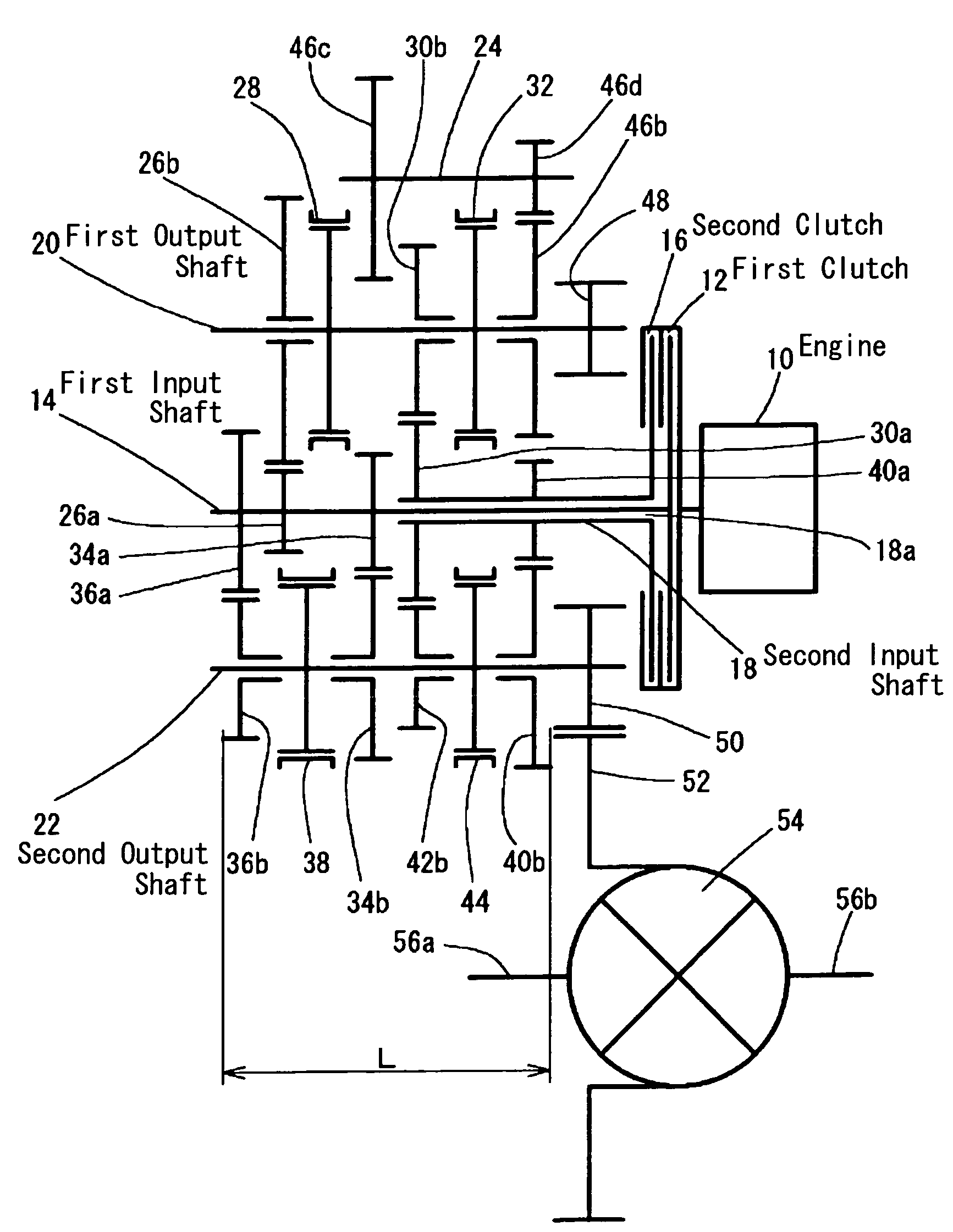
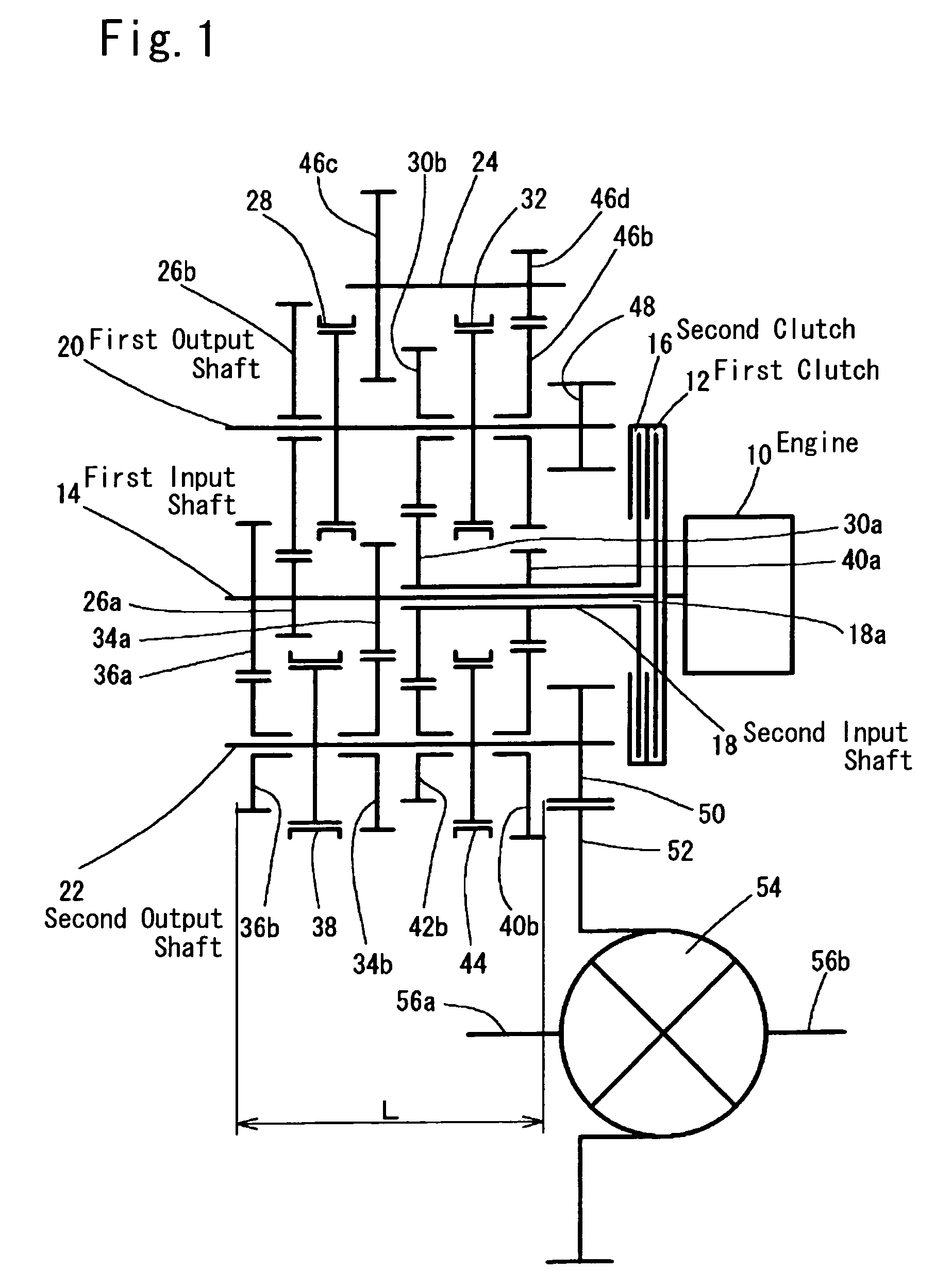
[0032]FIG. 1 is a skeleton diagram showing essential parts of a twin-clutch transmission according to the present invention.

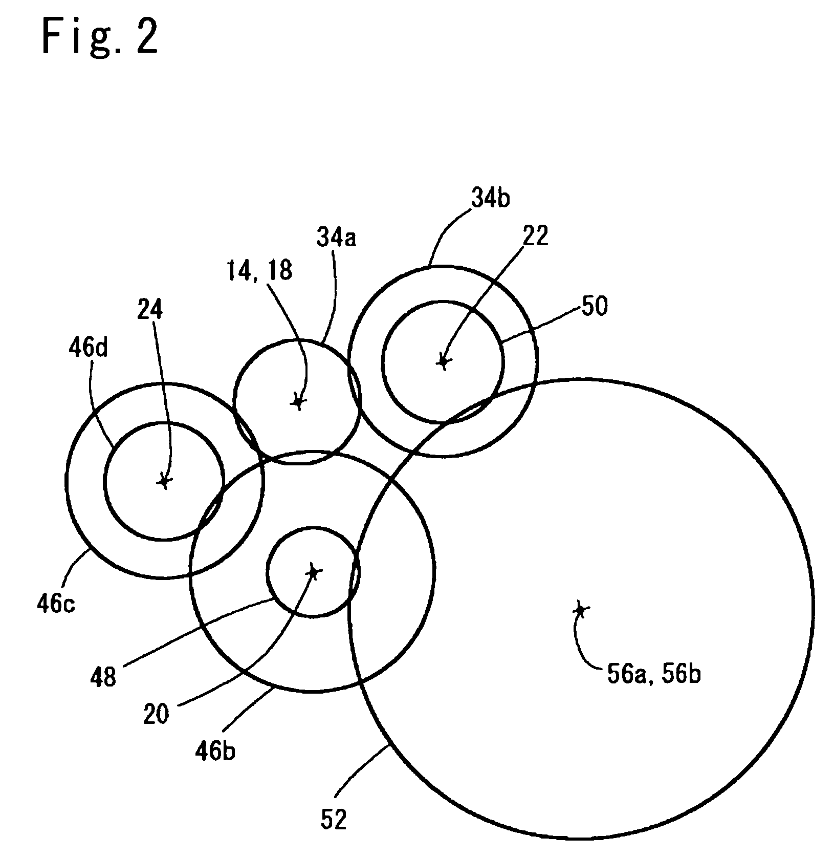
[0033]FIG. 1 shows a state in which the transmission with shafts thereof arranged as shown in FIG. 2 is spread out on a plane.

[0034]It should be noted that FIG. 2 shows the arrangement of the shafts as viewed from the left side in FIG. 1.

[0035]Power from an engine 10 can be transmitted in parallel to a first input shaft 14 via a first clutch 12 and to a second input shaft 18 via a second clutch 16.

[0036]The first input shaft 14 and the second input shaft 18 have a common axis, and the first input shaft 14 passes through a hole 18a of the second input shaft 18. A first output shaft 20, a second output shaft 22, and a sub shaft 24 are arranged in parallel with the first input shaft 14 and the second input shaft 18.

[0037]In FIG. 1, the distance between the first and second input shaft 14, 18 and the first output shaft 20 is set to be longer than the distance betwe...

second embodiment

[0092]Referring next to FIG. 5, a description will be given of a twin-clutch transmission according to the present invention. FIG. 5 is a skeleton diagram corresponding to FIG. 1.

[0093]Here, only parts different from those of the embodiment shown in FIG. 1 to 4 will be described; substantially the same parts are denoted by the same reference numerals, and description thereof is omitted.

[0094]The second embodiment differs from the embodiment shown in FIGS. 1 to 4 in that the transmission is a seven forward speed and one backward speed type, and the pairs of gears are arranged in a partially different way due to an increase in the number of gear speeds (gear ratios).

[0095]Specifically, the relationship in connection and arrangement of the engine 10, first clutch 12, first input shaft 14, second clutch 16, second input shaft 18, first output shaft 20, second output shaft 22, sub shaft 24, and so forth are the same as those of the embodiment shown in FIGS. 1 to 4, but the pairs of gears...


PUM


Abstract

A pair of first speed gears (26a, 26b) is provided between a first input shaft (14) and a first output shaft (20), and a pair of fourth speed gears (30a, 30b) is provided between a second input shaft (18) and the first output shaft. A pair of third speed gears (34a, 34b) and a pair of fifth speed gears (36a, 36b) are provided between the first input shaft and a second output shaft (22), and a pair of second speed gears (40a, 40b) and a pair of sixth speed gears (30a, 42b) are provided between the second input shaft and the second output shaft. A backward input gear (34a) integrated with the first input shaft and a backward output gear (46b) provided on the first output shaft are connected to each other via idler gears (46a, 46b) disposed on a sub shaft (24). By this arrangement the length in an axial direction of the transmission is made short.

Description

CROSS-REFERENCE TO RELATED APPLICATION[0001]This application is a U.S. National Phase Application of PCT International Application PCT / JP2004 / 000098.TECHNICAL FIELD[0002]The present invention relates to a twin-clutch transmission for an automobile, which is comprised of two clutches disposed between an engine and the transmission mechanism and is capable of alternately engaging and disengaging the two clutches in parallel with shifting operation so that gear speed can be sequentially changed without interrupting driving force.BACKGROUND ART[0003]Conventionally, there has been a twin-clutch transmission which is capable of alternately engaging and disengaging two clutches in parallel with shifting operation so that gear speed (gear ratio) can be sequentially changed without interrupting driving force, and in which a first clutch is disposed between the output shaft of an engine and a first input shaft (first clutch output shaft) and a second clutch is disposed between the output shaf...

Claims


Application Information

Patent Timeline
Patent Type & Authority Patents(United States)
IPC IPC(8): F16H3/08B60T1/06F16D21/04F16D23/04F16H3/00F16H3/093
CPCF16D21/04F16D23/04F16H3/006F16H3/093Y10T74/19233F16H2003/0931F16H2200/0052F16H2200/0056Y10T74/19228F16H63/48
Inventor HIRAIWA, KAZUYOSHI
Owner KYOWA METAL WORKS
Why Eureka
Try Eureka