Energy transfer systems

a technology of energy transfer and energy loop, which is applied in the direction of air heaters, sealing/packing, borehole/well accessories, etc., can solve the problems of thermal conductivity and installation difficulties, loop "insertion" difficulties, and the cost of certain prior art vertical ground source heat loops can account for nearly half of the total cost incurred, so as to facilitate the movement of the system

Inactive Publication Date: 2001-06-26
ENLINK GEOENERGY SERVICES
View PDF78 Cites 79 Cited by
  • Summary
  • Abstract
  • Description
  • Claims
  • Application Information

AI Technical Summary

Benefits of technology

Such systems using a filler material that includes a thermally conductive material in suspension with a gel material such as a suitable polymer and, in one aspect, with a cross-linking agent to assist in maintaining solids of the thermally conductive material in suspension with the polymer;
Such systems including a bottom membe

Problems solved by technology

The cost for the installation of certain prior art vertical ground source heat loops can account for nearly half of the total cost incurred in the installation of a geothermal heat pump system.
Several problems can arise in such methods: loop "insertion" difficulties caused by loop buoyancy; thermal conductivity and installation difficulties of borehole backfill materials; and environmental concerns.
Although the drilling of the hole may be relatively easy, certain problems may be encountered in inserting the loop.
This pipe material also has relatively poor stiffness.
Since the pipe has poor longitudinal stiffness, the pipe tends to bend or curl inside the well, creating additional frictional drag against the well wall until the pipe can be pushed no deeper.
Even when the pipe is filled with water, the loop still maintains considerable buoyancy because the drilled hole is filled with dense drilling mud.
However, the result is residual heavy drilling fluid in the well, creating a very dense slurry of clay, sand, rock, etc.--with resulting high buoyancy and low surface tension.
The considerable efforts made to overcome buoyancy of the loop caused by the density of the drill fluid are time consuming, expensive, and hazardous to the integrity of the loop.
Great expense and many tests and studies have been performed in a search for an optimum thermally conductive material that can be economically placed in the annular space between the loop pipe and the wellbore wall.
The concern is that over time, the water table may drop, leaving an insulating airspace between the loop and the borehole.
This insulating airspace results in "hot loops", and the heat pump system either works poorly or not at all.
Although these grouts seem to work well in testing, there is great resistance from the field installers.
The mixture can be expensive to ha

Method used


Image

  • Energy transfer systems
  • Energy transfer systems
  • Energy transfer systems

Examples


Embodiment Construction

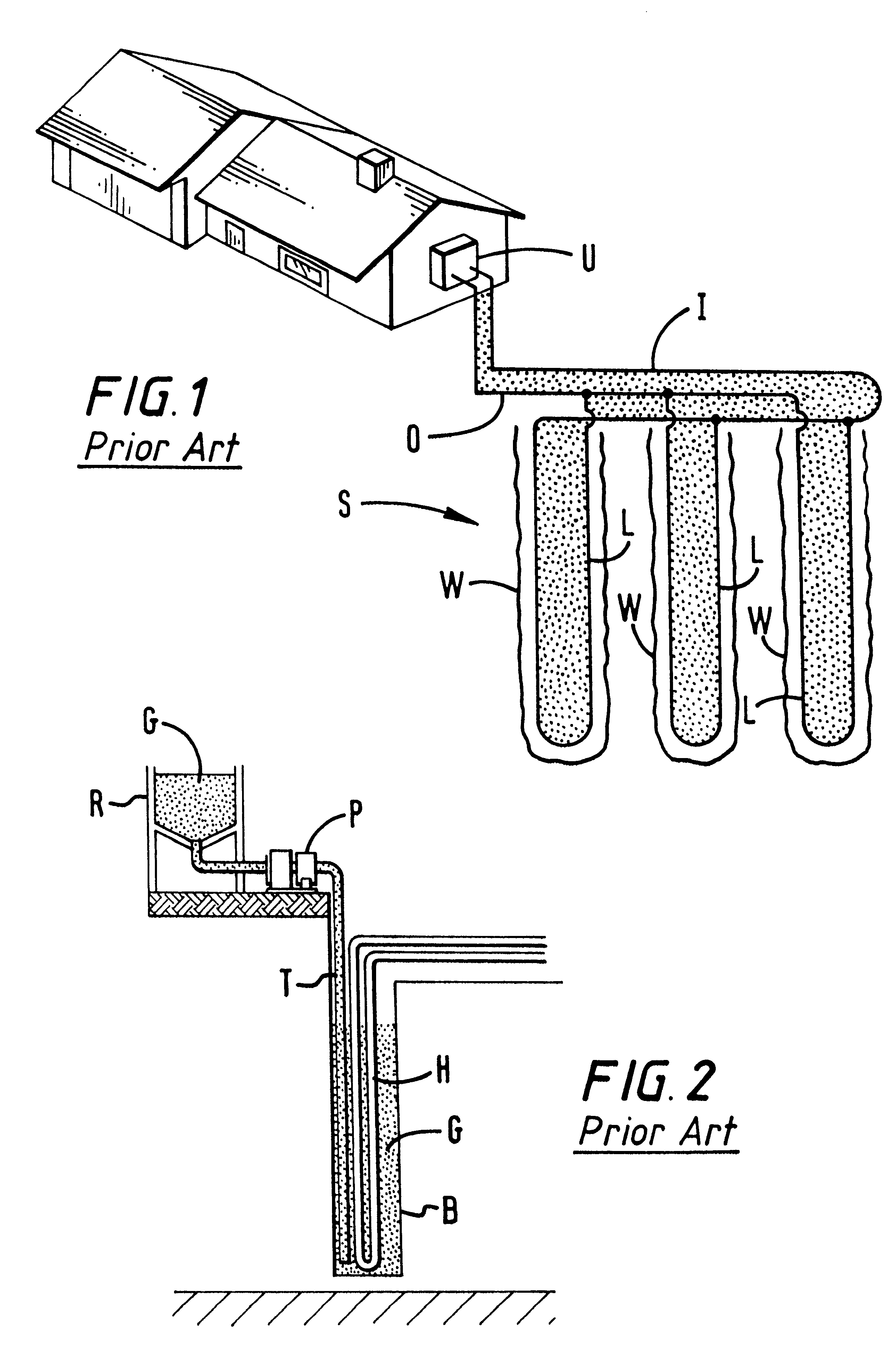
Referring now to FIG. 1, a prior art underground heat exchange pipe loop system S has a plurality of wellbores W, each e.g. about 250 feet deep and 4 to 4.5 inches in diameter, which are preferably, between about ten feet to fifteen feet apart. Water flows from a building's processing unit U in an inlet pipe I into each inlet side of a plurality of pipe heat exchange loops L and then flows up in each outlet side of the loops L to an outlet pipe O which is in fluid communication with the processing unit U. Pipes I and O are typically about 45 feet long for a three loop system as shown (preferably about ten to fifteen feet between each loop).

FIG. 2 illustrates a prior art system and method for grouting a wellbore such as the wellbores W in FIG. 1. After a pipe heat exchange loop H is installed in a wellbore B, a grout pipe T is inserted into the wellbore B. A grout pump P then pumps grout G from a reservoir R down the grout pipe T from which it flows into the wellbore B.
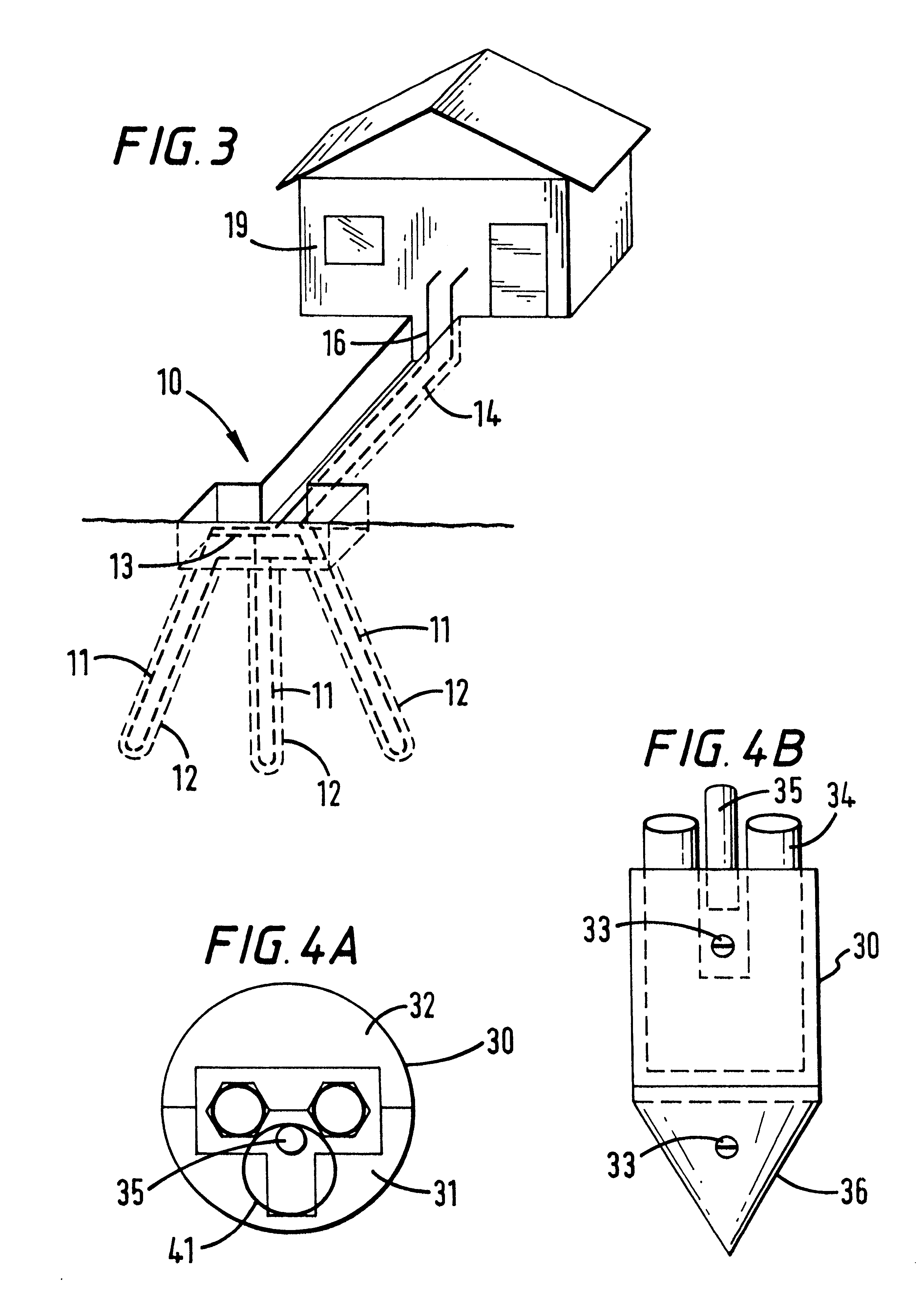
FIG. 3 shows a...


PUM


Abstract

An earth energy loop transfer system with a moving energy transfer fluid, the system for transferring energy for an entity, the system having means for measuring an amount of energy transferred for the entity to or from the moving energy transfer fluid, and means for invoicing the entity for the amount of energy transferred. The system including means for calculating a price for the amount of energy transferred, said invoicing based on said price. The system including means for transmitting a signal indicative of a measured amount of energy transferred from the means for measuring to the means for invoicing. Methods are disclosed for using such systems to measure and calculate an amount of energy transferred and/or to invoice an entity for the transferred energy.

Description

1. Field of the InventionThe present invention is directed to underground heat exchange systems; to apparatus and methods for installing a loop of pipe in a hole in the earth; and to thermally conductive filler materials for emplacement between the pipe loop and the interior hole wall.2. Description of Related ArtThe prior art discloses a wide variety of earth heat exchange systems and methods for using energy transferred by such systems.The prior art discloses the use of a common grout, typically a bentonite clay mixture, for use as a thermally conductive material between a pipe loop of an underground heat exchange system and the interior of a hole in which the loop is positioned.The cost for the installation of certain prior art vertical ground source heat loops can account for nearly half of the total cost incurred in the installation of a geothermal heat pump system. In certain aspects, the heat loop installation consists of drilling a vertical well, placing a thermoplastic pipe...

Claims


Application Information

Patent Timeline
IPC IPC(8): E21B33/13E21B23/00F28F27/00F25B30/06F25B30/00F28D20/00
CPCF25B30/06F28D20/0052F28F27/00E21B23/00E21B33/13F24J3/083Y02E10/125Y02E60/142F24J2003/088F24J2003/089F24J2200/04F24S2201/00F24T10/15F24T2010/53F24T2010/56Y02E10/10Y02E60/14
Inventor AMERMAN, THOMAS R.JOHNSON, JR., HOWARD E.
Owner ENLINK GEOENERGY SERVICES
Why Eureka
Try Eureka