Linear motor

A linear motor and excitation technology, applied in the direction of electrical components, electromechanical devices, electric components, etc., can solve the problem of limiting the force density of linear motors, achieve the effect of compact structure, small size, and enhanced driving ability

Active Publication Date: 2017-06-13
WELLING WUHU MOTOR MFG
View PDF3 Cites 1 Cited by
  • Summary
  • Abstract
  • Description
  • Claims
  • Application Information

AI Technical Summary

Problems solved by technology

However, in the existing stator-excited permanent magnet linear motor, in a certain space, the volume of the permanent magnet and the area of ​​the slot restrict each other, which limits the improvement of the force density of the linear motor.

Method used


Image

  • Linear motor
  • Linear motor
  • Linear motor

Examples


Embodiment 1

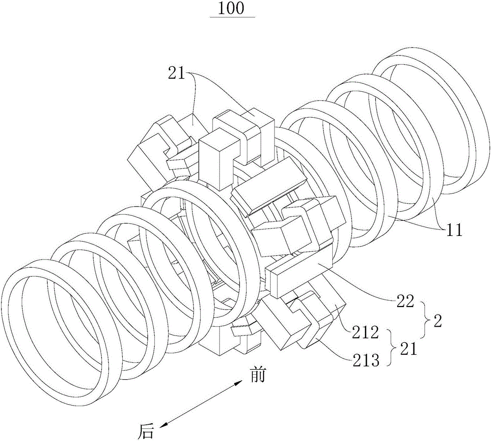
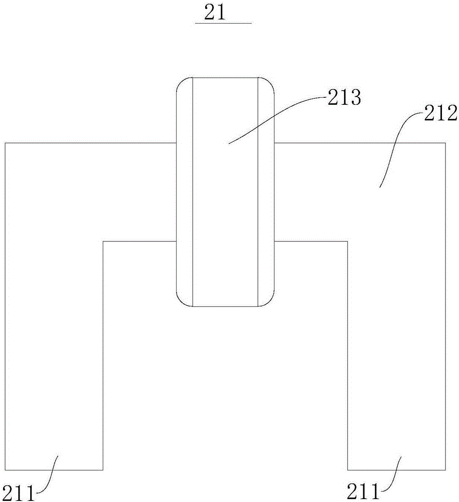
[0064] refer to figure 1 , the linear motor 100 includes a motor primary 2 and a motor secondary 1, wherein the motor primary 2 and the motor secondary 1 are spaced apart to form an air gap 3, and the motor primary 2 includes a plurality of winding excitation sides 21 and a plurality of permanent magnet excitation Side 22 , the motor secondary 1 comprises a reluctance side comprising a reluctance core 11 and a fixing plate.

[0065] Specifically, the reluctance side is composed of a reluctance iron core 11 made of a high magnetic permeability material and a fixing plate made of a non-magnetic material. arrangement, and the reluctance iron core is circular.

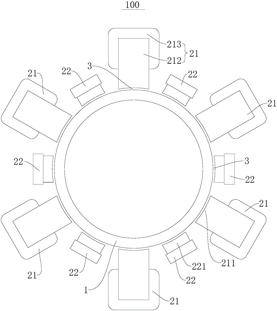
[0066] A plurality of winding excitation sides 21 and a plurality of permanent magnet excitation sides 22 are evenly spaced on the outer side of the reluctance core 11 in the radial direction along the circumferential direction of the reluctance core 11, and a plurality of winding excitation sides 21 and a plurality of pe...

Embodiment 2

[0070] Such as Figure 5 and Figure 6As shown, the structure of this embodiment is roughly the same as that of Embodiment 1, wherein the same components use the same reference numerals, the only difference is that the plurality of winding excitation sides 21 and the plurality of permanent magnet excitation described in Embodiment 1 side 22 is arranged on the outer side of the reluctance core 11 in the radial direction, while the multiple winding excitation sides 21 and the multiple permanent magnet excitation sides 22 in the second embodiment are arranged on the radially outer side of the reluctance core 11 to the inside.


PUM


Abstract

The invention discloses a linear motor. The linear motor comprises a motor secondary part and a motor primary part. The motor secondary part comprises a magnetic conductive magnetic resistance side, the magnetic resistance side comprises a plurality of annular magnetic resistance iron cores distributed at intervals, the motor primary part and the motor secondary part are arranged in a spaced mode to form an air gap, the motor primary part comprises a plurality of winding excitation sides and a plurality of permanent magnet sides, the winding excitation sides are distributed at intervals in the peripheral direction of the magnetic resistance iron cores and are applicable to induction to generate a magnetic field, the multiple winding excitation sides and the multiple permanent magnet sides are arranged in a staggered mode in the peripheral direction of the magnetic resistance iron cores, and the permanent magnet excitation sides and the winding excitation sides are matched. According to the linear motor, the motor primary part can be pushed to move in the laying direction of the magnetic resistance iron core of the motor primary part, the force density is large, and the linear motor is suitable for various linear direct-dive occasions.

Description

technical field [0001] The invention relates to the technical field of motors, in particular to a linear motor. Background technique [0002] In the related art, the stator excitation permanent magnet motor has the advantage that the amount of permanent magnets is not limited by the stroke. However, in the existing stator-excited permanent-magnet linear motor, within a certain space, the volume of the permanent magnet and the area of ​​the slot restrict each other, which limits the improvement of the force density of the linear motor. Contents of the invention [0003] The present invention aims to solve at least one of the technical problems existing in the prior art. Therefore, the present invention proposes a linear motor, which has a high force density and is suitable for various linear direct drive applications. [0004] According to the linear motor of the present invention, it includes: a motor secondary, the motor secondary includes a magnetic reluctance side, an...

Claims


Application Information

Patent Timeline
Patent Type & Authority Applications(China)
IPC IPC(8): H02K41/03
Inventor 吴迪陈金涛诸自强王洪晓
Owner WELLING WUHU MOTOR MFG
Why Eureka
Try Eureka