
Fur storage device
A storage device and fur technology, which is applied to the legs of general furniture, accessories of furniture, adjustable cabinets, etc., can solve the problems that the racks cannot be well isolated, the racks are inconvenient to move, and are not uniform.
- Summary
- Abstract
- Description
- Claims
- Application Information
AI Technical Summary
Problems solved by technology
Method used
Image

Examples
Embodiment Construction
[0020] The following will clearly and completely describe the technical solutions in the embodiments of the present invention with reference to the accompanying drawings in the embodiments of the present invention. Obviously, the described embodiments are only some, not all, embodiments of the present invention.
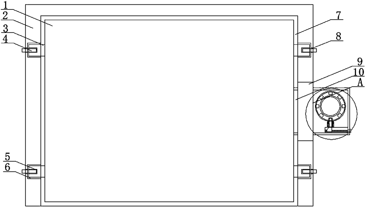
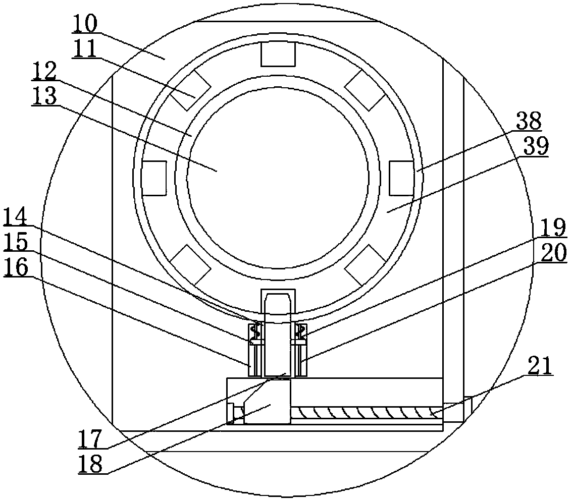
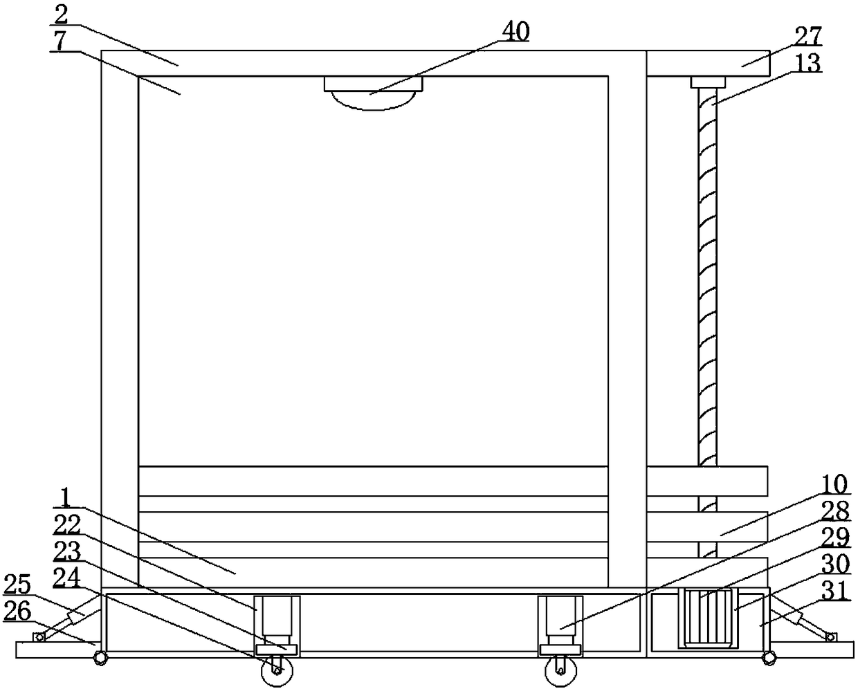
[0021] refer to Figure 1-5, a storage device for fur, comprising a bearing block 2, one side of the bearing block 2 is provided with a bearing groove 7, and two first slide grooves 6 parallel to each other are arranged on the opposite side walls of the bearing groove 7, the first A plurality of first sliders 3 are installed in the chute 6 from top to bottom, and the first slider 3 moves in the first chute 6, and the four first sliders 3 on the same side form a group, and the same group The bearing plate 1 is jointly fixed between the first sliders 3 to facilitate the lifting of the bearing plate 1. A plurality of second limiting holes 8 are equidistantly arranged on...
PUM
 Abstract
Description
Claims
Application Information