Voltage control method and device for distribution network

A voltage control method and distribution network technology, applied in the direction of circuit devices, AC network voltage adjustment, electrical components, etc., can solve the problems that are difficult to solve such as distribution network voltage limit, lack of distribution network communication facilities, low automation level, etc.

Active Publication Date: 2020-09-29
海南电网有限责任公司文昌供电局
View PDF6 Cites 0 Cited by
  • Summary
  • Abstract
  • Description
  • Claims
  • Application Information

AI Technical Summary

Problems solved by technology

[0004] Based on this, it is necessary to provide a distribution network system for the lack of communication facilities, low automation level, inability to perform centralized reactive power voltage control, and difficulty in solving the defects of distribution network voltage limit with DG grid-connected points. Voltage control method and device

Method used


Image

  • Voltage control method and device for distribution network
  • Voltage control method and device for distribution network
  • Voltage control method and device for distribution network

Examples


Embodiment 1

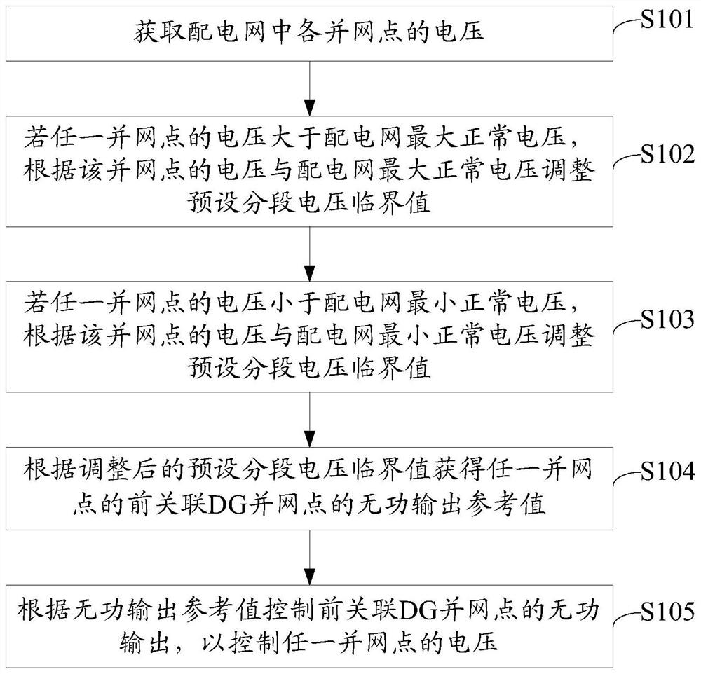
[0032] figure 1 It is the flow chart of the voltage control method of the distribution network in the first embodiment, such as figure 1 As shown, steps S101 to S105 are included:

[0033] S101: Obtain the voltage of each grid connection point in the distribution network; wherein the grid connection point includes a DG grid connection point and a feeder end node;

[0034] Among them, the distribution network includes multiple nodes, the node connected to the DG is the DG grid-connecting point, and the node with the farthest distance from the head end bus of the distribution network is the feeder end node.

[0035] S102: If the voltage of any grid connection point is greater than the maximum normal voltage of the distribution network, adjust the preset segment voltage threshold according to the voltage of the grid connection point and the maximum normal voltage of the distribution network;

[0036] Among them, the voltage of the distribution network has a normal fluctuation range, the u...

Embodiment 2

[0072] Figure 4 It is the module structure diagram of the voltage control device of the distribution network in the second embodiment, such as Figure 4 As shown, the voltage control device of the distribution network includes modules 501 to 505:

[0073] The voltage obtaining module 501 is used to obtain the voltage of each grid connection point in the distribution network; wherein the grid connection point includes a DG grid connection point and a feeder end node;

[0074] The first adjustment module 502 is configured to adjust the preset segment voltage threshold according to the voltage of the grid connection point and the maximum normal voltage of the distribution network when the voltage of any grid connection point is greater than the maximum normal voltage of the distribution network;

[0075] In an optional implementation manner, the first adjustment module 502 includes:

[0076] The first difference obtaining module obtains the difference between the voltage of the grid conn...


PUM


Abstract

The invention relates to a voltage control method and device for a distribution network. When the voltage at a grid-connected point of a distribution network exceeds the limit, that is, the voltage atany grid-connected point is greater than the maximum normal voltage of the distribution network or less than the minimum normal voltage of the distribution network, a preset segmented voltage critical value is adjusted based on the maximum normal voltage or the minimum normal voltage of the distribution network and thus a reactive output reference value of a previous associated DG grid-connectedpoint at nay grid-connected is obtained based on the adjusted preset segmented voltage critical value; and the reactive output of the previous associated DG grid-connected point is controlled based onthe reactive output reference value to control the voltage of any grid-connected point. Therefore, limit exceeding by the voltage at any grid-connected point is prevented and the voltage of the distribution network is constrained to be in a normal range.

Description

Technical field [0001] The present invention relates to the technical field of power system control, in particular to a method and device for controlling reactive power output of a distribution network. Background technique [0002] Distributed power generation system is one of the forms of efficient utilization of new energy and will occupy an important position in the global future energy structure. DG (Distributed Generation) grid-connected points have the characteristics of strong randomness and obvious intermittentness, which makes the output fluctuate greatly and the fluctuation frequency is also irregular. And as the penetration rate of DG grid-connected points increases, the operation of the power system And the analysis has also undergone profound changes. The DG grid-connection point alone is not conducive to the safe and stable operation of the grid. After the DG grid-connected point is connected to the feeder, the main impact on the distribution network is that it ch...

Claims


Application Information

Patent Timeline
Patent Type & Authority Patents(China)
IPC IPC(8): H02J3/16H02J3/38
CPCH02J3/16H02J3/381H02J3/382Y02E40/30
Inventor 叶保璇吴育武童炳璋王康坚王禄庆
Owner 海南电网有限责任公司文昌供电局
Why Eureka
Try Eureka