Differential dual floating gate circuit and method for programming

A floating gate and circuit technology, applied in electrical analog memory, instrument, static memory, etc., can solve the problem of fast trapping of tunnel oxide

Inactive Publication Date: 2006-03-29
INTERSIL INC
View PDF4 Cites 0 Cited by
  • Summary
  • Abstract
  • Description
  • Claims
  • Application Information

AI Technical Summary

Problems solved by technology

Known disadvantages of dual conduction digital programming of floating gates include: larger total voltage required to provide dual conduction voltage, and faster tunnel oxide trap-up because more tunnel current is required
Furthermore, prior art bandgap voltage references typically draw relatively large currents, ie greater than 10 μA

Method used


Image

  • Differential dual floating gate circuit and method for programming
  • Differential dual floating gate circuit and method for programming
  • Differential dual floating gate circuit and method for programming

Examples


Embodiment Construction

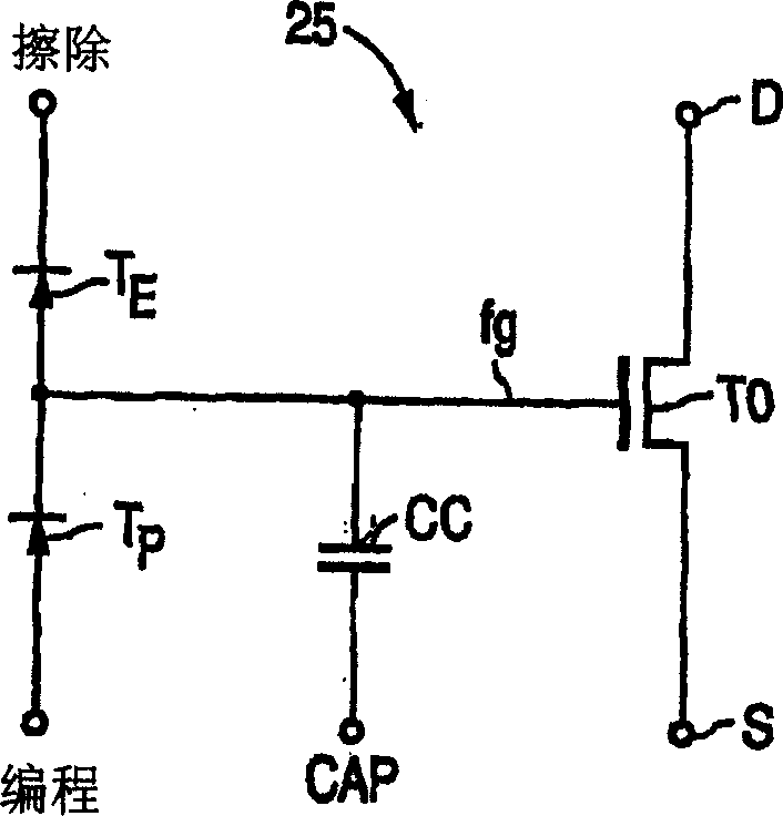
[0043] image 3 is a circuit diagram of a differential single floating gate circuit 30 for accurately setting a floating gate to an analog voltage during a high voltage set mode or set period in accordance with the present invention. Figure 4A is a circuit diagram of a differential double floating gate circuit 40 according to another embodiment of the present invention. Circuit 40 is also used to accurately set the floating gate to an analog voltage during the high voltage set mode. Once the analog voltage level is set, both circuit 30 and circuit 40 can be configured as a precision voltage comparator circuit with an embedded voltage reference or as a precision voltage reference circuit during a read mode. Circuits 30 and 40 are preferably implemented as integrated circuits fabricated using standard CMOS processing techniques. Since the sequence used during the setup mode is similar for both circuits, circuit 30 and the method of programming the floating gate with circuit 30...


PUM


Abstract

A method and circuit for setting a reference voltage (Vout) in a dual floating gate circuit is disclosed. During a set mode, a first and second floating gates (T1, T2) are programmed to different charge levels that are a function of an input set voltage (Vset) capacitively coupled to the first floating gate during the set mode. During a read mode, this difference in charge level is used by the dual floating gate circuit to generate a reference voltage (Vout) that is a function of the input set voltage (Vset), and is preferably equal to the input set voltage (Vset).

Description

technical field [0001] The present invention relates to methods and circuits for an accurate voltage reference, and more particularly to differential circuits that use feedback loops and double conduction of tunnel devices to accurately program desired charge levels on floating gates. Background technique [0002] Programmable analog floating gate circuits have been used since the early 1980's in applications requiring only modest absolute voltage accuracy over time, such as 100-200 mV absolute voltage accuracy over time. Such devices are commonly used to provide long-term non-volatile storage of charge on floating gates. A floating gate is an isolated piece of conductive material that is electrically isolated from the substrate but capacitively coupled to the substrate or other conductive layers. In general, the floating gate forms the gate of a MOS transistor which is used to read the charge level on the floating gate without causing any charge to leak therethrough. [0...

Claims


Application Information

Patent Timeline
Patent Type & Authority Applications(China)
IPC IPC(8): G11C16/06G11C27/00
CPCG11C27/005
Inventor W·欧文
Owner INTERSIL INC
Why Eureka
Try Eureka