Check patentability & draft patents in minutes with Patsnap Eureka AI!

Garbage incinerator with exhaust gas purification function

A waste incineration and exhaust gas purification technology, applied in the direction of incinerators, combustion types, combustion methods, etc., can solve problems such as polluting the environment, secondary pollution, and endangering human health, and achieve reduced incineration time, lower temperature requirements, and improved thermal efficiency. The effect of utilization

Active Publication Date: 2020-12-08
郑多多
View PDF4 Cites 0 Cited by
  • Summary
  • Abstract
  • Description
  • Claims
  • Application Information

AI Technical Summary

Problems solved by technology

[0002] With the continuous improvement of people's living standards and the continuous expansion of production scale, the problem of garbage pollution is becoming more and more serious. Garbage contains heavy metals, organic compounds, and aromatic hydrocarbons, chlorinated organic compounds, and polychlorinated biphenyls. If it is not effectively disposed of, it will cause a series of environmental pollution problems such as soil, water, and air, endanger human health, destroy the ecological environment, occupy land and affect urban landscapes, etc.
[0003] The existing garbage disposal equipment has the following problems: the current garbage disposal equipment is to put the garbage into the incinerator for combustion, and the high temperature incineration plays the role of solidifying harmful substances and sterilizing and disinfecting, but the incineration process will inevitably produce secondary waste. Pollution, causing incineration flue gas to fail to meet the emission standards, polluting the environment and endangering human health

Method used


Image

  • Garbage incinerator with exhaust gas purification function
  • Garbage incinerator with exhaust gas purification function
  • Garbage incinerator with exhaust gas purification function

Examples


Embodiment Construction

[0026] Below in conjunction with accompanying drawing and embodiment, further elaborate the present invention. In the following detailed description, certain exemplary embodiments of the invention are described by way of illustration only. Needless to say, those skilled in the art would realize that the described embodiments can be modified in various different ways, all without departing from the spirit and scope of the present invention. Accordingly, the drawings and description are illustrative in nature and not intended to limit the scope of the claims.

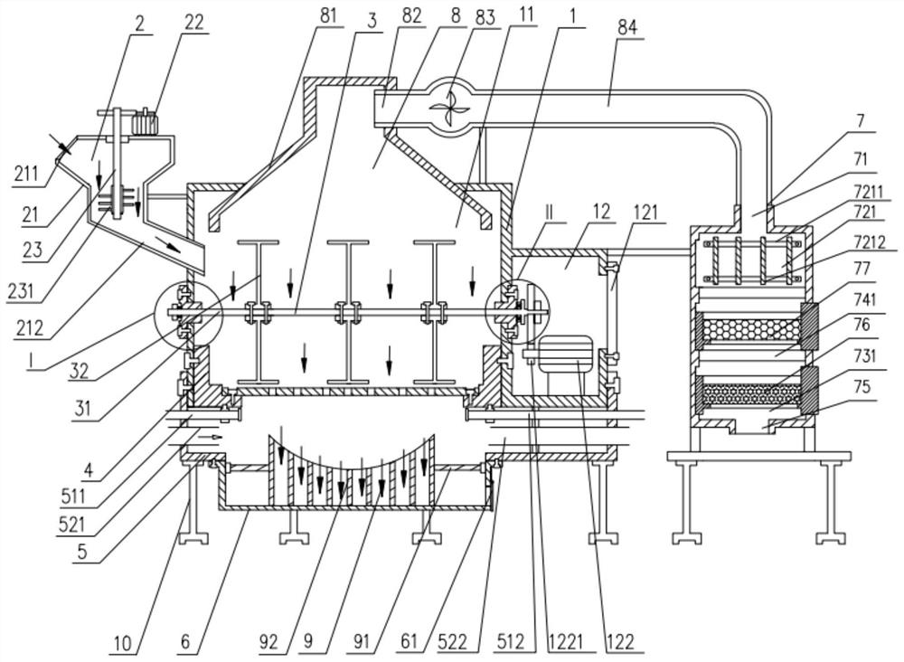
[0027] Such as Figure 1 to Figure 6 As shown, the waste incineration device with exhaust gas purification function according to this embodiment includes a main chamber 1, a pulverizer 2, an agitator 3, an air supply chamber 5, a combustion grid assembly 4, an exhaust gas collection assembly 8 and a purification device 7 The upper left side of the main chamber 1 is connected with a pulverizer 2. The main chamber 1 inclu...


PUM


Abstract

The invention discloses a garbage incineration device with a waste gas purification function. The garbage incineration device comprises a main chamber, a crusher, a stirrer, an air supply chamber, a combustion grid assembly, a waste gas collection assembly and a purification device. The upper portion of the left side of the main chamber is connected with the crusher. A drive motor for driving a drive gear is arranged in a stirring drive chamber. The stirrer is arranged in an incineration chamber. Multiple stirring paddles are arranged on a stirring main shaft, the left side of the stirring main shaft is connected with the side wall of the incineration chamber through a first connecting flange, and the right side of the stirring main shaft is provided with a pressing protrusion. The combustion grid assembly comprises an arc partition plate. Middle row holes and side holes formed in the two sides of the middle row holes are formed in the arc partition plate. The waste gas collection assembly is arranged at the upper end of the main chamber, and the air supply chamber is arranged below the main chamber. According to the garbage incineration device, through the arrangement of the crusher, the stirrer and the purification device, garbage can be fully incinerated, generated waste gas is subjected to purification treatment, and pollution waste gas emission is reduced. The garbage incineration device is suitable for being widely applied to garbage treatment.

Description

technical field [0001] The invention relates to the technical field of garbage treatment, in particular to a garbage incineration device with exhaust gas purification function. Background technique [0002] With the continuous improvement of people's living standards and the continuous expansion of production scale, the problem of garbage pollution is becoming more and more serious. Garbage contains heavy metals, organic compounds, and aromatic hydrocarbons, chlorinated organic compounds, and polychlorinated biphenyls. If it is not effectively disposed of, it will cause a series of environmental pollution problems such as soil, water, and air, endanger human health, destroy the ecological environment, and occupy land and affect urban landscapes. [0003] The existing garbage disposal equipment has the following problems: the current garbage disposal equipment is to put the garbage into the incinerator for combustion, and the high temperature incineration plays the role of so...

Claims


Application Information

Patent Timeline
Patent Type & Authority Patents(China)
IPC IPC(8): F23G5/033F23G5/02F23G5/44F23J15/02F23J1/00
CPCF23G5/006F23G5/02F23G5/033F23G5/44F23G2201/80F23J1/00F23J15/02F23J2215/40
Inventor 不公告发明人
Owner 郑多多
Features
  • R&D
  • Intellectual Property
  • Life Sciences
  • Materials
  • Tech Scout
  • Unparalleled Data Quality
  • Higher Quality Content
  • 60% Fewer Hallucinations
Learn More