

Combustion device
A combustion device and combustion tube technology, applied in combustion methods, combustion equipment, combustion of solid fuels, etc., can solve the problems of affecting fuel, low thermal efficiency, poor continuity of combustion and heat supply, etc., and achieve the effect of improving ventilation and improving thermal efficiency.
- Summary
- Abstract
- Description
- Claims
- Application Information
AI Technical Summary
Problems solved by technology
Method used
Image

Examples
Embodiment 1
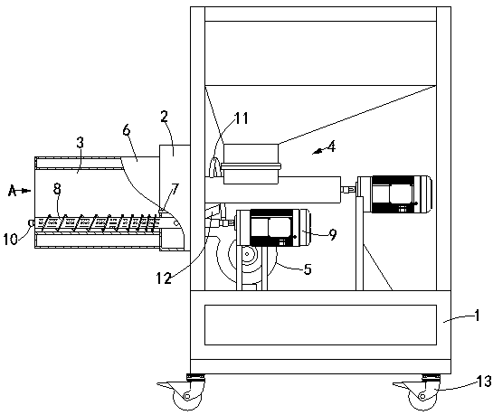
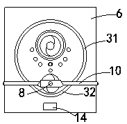
[0024] Figure 1-3 The combustion device shown includes a frame body 1, a box body 2 arranged on the frame body 1, a combustion pipe 3 arranged on the box body 2, a screw conveyor 4 arranged on the box body 2, an air outlet and the box body 2 The fan 5 connected to the inner cavity, the air distribution pipe shell 6 that is set on the combustion pipe 3 and fixedly connected with the box body 2, and the igniter 7 that is installed on the box body 2 and whose heating end is located at the lower part of the combustion pipe 3 , and a pusher mechanism; one end of the combustion tube 3 discharging hot smoke is called the front end, and the other end is called the rear end; the combustion tube 3 includes an upper arc plate 31, which is connected to the lower end of the upper arc plate 31 to form a The lower circular arc plate 32 of the combustion chamber; the diameter of the lower circular arc plate 32 is smaller than the diameter of the upper circular arc plate 31; a number of venti...
Embodiment 2
[0032] Figure 4 The combustion device shown, wherein, the lower part of the hopper 41 of the screw conveyor 4 is provided with a discharge pipe 42, and the discharge pipe 42 is provided with a slide valve 43, after the heating work is completed, the discharge pipe can be Most of the materials in the hopper are quickly discharged to improve the convenience of operation. All the other are basically the same as Example 1.
Embodiment 3
[0034] Figure 5 In the combustion device shown, the screw conveyor 4 includes a feeding hopper 41 ; it also includes an additional hopper 14 arranged at the upper end of the feeding hopper 41 . The additional hopper can increase the supply of materials, especially at night, which can avoid the frequent waking up of operators to add materials at night.
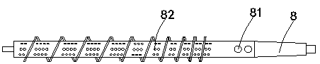
[0035] The present invention can push and crush the coked blocks in the combustion tube by setting the spiral conveying shaft with gradually changing pitch, so as to avoid the blockage of the coked blocks and the influence of the coked blocks on the air flow. The fuel is fully burned in the initial stage, and the subsequent screw pitch can gradually accelerate the discharge of coke after combustion. At the same time, by reasonably setting the shape of the combustion tube, the propulsion ability of the screw to the material can be greatly improved, avoiding material accumulation, and further improving the combustion efficiency...
PUM
 Abstract
Description
Claims
Application Information