
Drainage structure for accelerating consolidation of sludge soil dredged body of dam engineering and construction method thereof
A drainage structure and engineering technology, which is applied in the direction of basic structure engineering, soil protection, construction, etc., can solve the problems of low drainage efficiency of drainage structure, long land dehydration and consolidation period, etc., so as to improve the effective stress of soil and enhance drainage capacity , Accelerate the effect of soil consolidation
- Summary
- Abstract
- Description
- Claims
- Application Information
AI Technical Summary
Problems solved by technology
Method used
Image

Examples
Embodiment 1
[0048] The present invention will be described in further detail below in conjunction with the accompanying drawings.
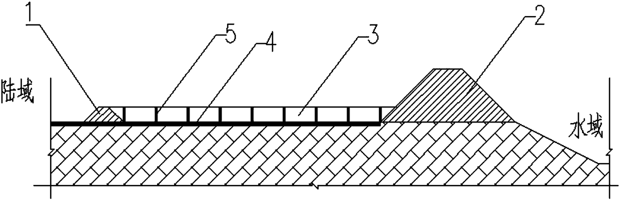
[0049] Such as figure 1 As shown, a drainage structure to speed up the consolidation of the silt body in the silt discharge and embankment consolidation project includes a dike 1, a levee 2, a silt back area 3 between the dike 1 and the levee 2, and a drainage system arranged in the silt back area 3 The drainage channel includes a plurality of drainage blind ditches 4 arranged horizontally at the bottom of the silt area, and a plurality of drainage sand wells 5 arranged vertically in the silt area 3 .
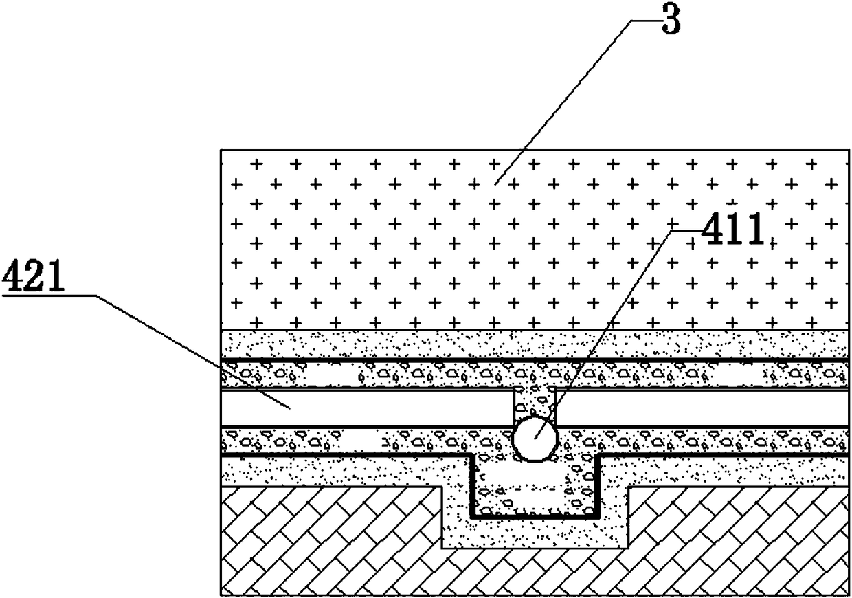
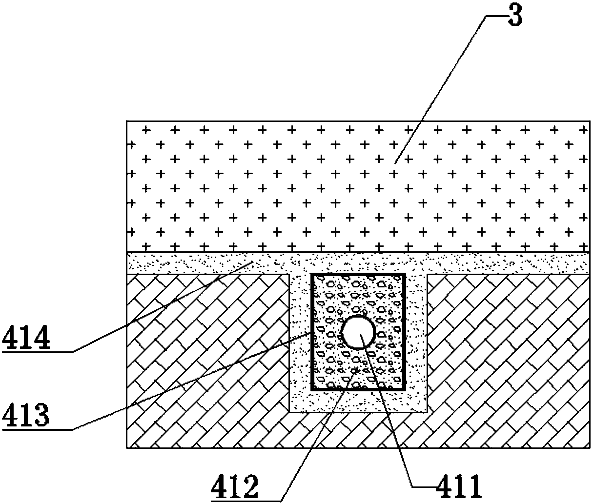
[0050] Such as Figure 2-Figure 5 As mentioned above, the blind drainage ditch 4 includes a main blind drainage ditch 41 and a secondary blind drainage ditch 42; the main blind drainage ditch 41 includes a main perforated pipe 411, a main drainage pebble layer 412, a main drainage nonwoven Cloth layer 413 and main drainage coarse sand layer 414, secondary dr...
Embodiment 2
[0054] Such as Figure 7 As shown, the thickness of the silt back body is thicker, and the construction is divided into two phases. The drainage channel is provided with upper and lower layers, and the distance between the two layers of drainage channels is 3m. The rest of the structure of this embodiment is the same as that of Embodiment 1.
[0055] The drainage system includes vertical drainage system and horizontal drainage system.
[0056] The vertical drainage system is a bagged sand well with a diameter of 7cm, and the design spacing is 1.0m to 1.5m; the sand well is an ideal artificial vertical drainage and decompression channel, and the ultra-static pore water in the soil must be discharged to the ground along the drainage channel .
[0057] According to the actual situation of the project, if the silt back area is thicker, it can be constructed in stages, and the thickness of each layer in each stage is 3m~6m; because the thickness of each layer is not thick, the ver...
PUM
 Abstract
Description
Claims
Application Information