Pneumatic disc brake caliper assembly

A disc brake and assembly technology, applied in the direction of brake type, axial brake, brake components, etc., can solve the problems that the service life cannot be effectively guaranteed, the overall rigidity and strength are not good, and the processing accuracy is high. Achieve the effect of ensuring work stability and service life, suppressing eccentric wear and dragging problems, and high precision

Pending Publication Date: 2018-10-09
ZHEJIANG GUOCHANG MACHINERY CO LTD
View PDF1 Cites 2 Cited by
  • Summary
  • Abstract
  • Description
  • Claims
  • Application Information

AI Technical Summary

Problems solved by technology

[0004] The above-mentioned pneumatic disc brake makes the booster gap adjustment assembly wrapped by the setting of the cage, which is convenient for assembly, but the caliper body is a split structure, and the upper caliper body and the lower caliper body are connected by bolts, so the overall rigidity and strength are not good. The service life is short. In order to install the booster gap adjustment assembly, ensure the guiding performance and ensure the reliability of the roller positioning, the internal processing precision of the upper clamp body is required to be high, and the processing is inconvenient. In addition, the gap compensation mechanism is a torsion spring and an adjustment sleeve. The accuracy of the gap mainly depends on the manufacturing precision of the torsion spring, which cannot effectively guarantee the service life

Method used


Image

  • Pneumatic disc brake caliper assembly
  • Pneumatic disc brake caliper assembly
  • Pneumatic disc brake caliper assembly

Examples


Embodiment Construction

[0031] The following are specific embodiments of the present invention and in conjunction with the accompanying drawings, the technical solutions of the present invention are further described, but the present invention is not limited to these embodiments.

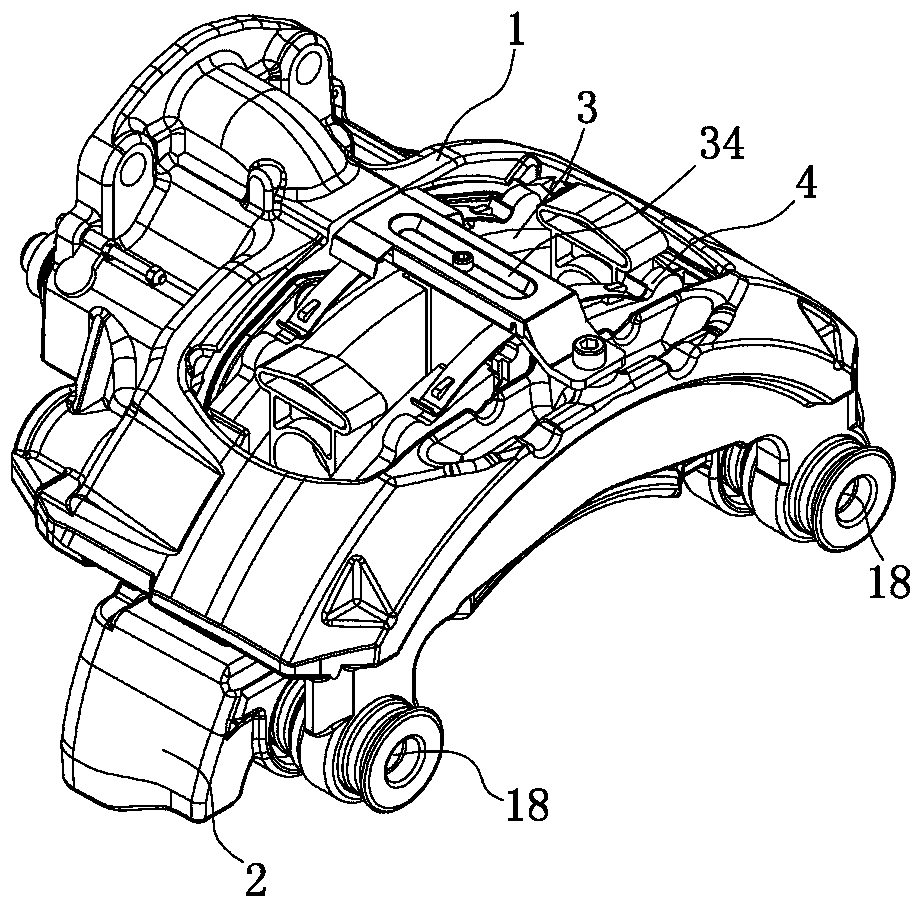
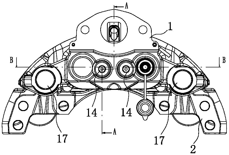
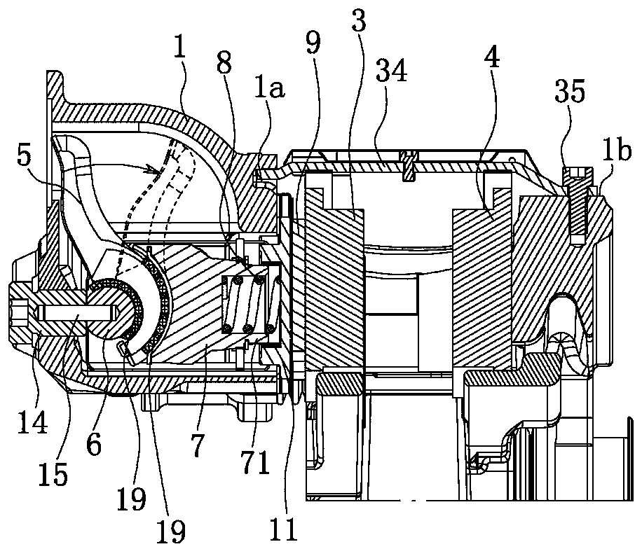
[0032] like figure 1 , figure 2 , image 3 , Figure 4 , Figure 5 and Image 6As shown, the pneumatic disc brake caliper assembly includes a caliper body 1, a force booster gap adjustment assembly and a bracket 2, and the main friction block 3 and the auxiliary friction block 4 are arranged on both sides of the bracket 2, and the caliper body 1 has a capacity for accommodating the booster. The chamber of the gap adjustment assembly, the booster gap adjustment assembly includes a pressure arm 5, a fixed rotating shaft 6, a thrust bracket 7, a bracket return spring 8, a pressure plate 9 and two push rods 10, and the clamp body 1 is fixedly connected with the cavity The cover plate 11 of the chamber cover, the outer en...


PUM


Abstract

The invention provides a pneumatic disc brake caliper assembly, and belongs to the technical field of vehicle accessories. By adoption of the pneumatic disc brake caliper assembly, the problems that an existing pneumatic disc brake caliper is poor in strength, inconvenient to machine and the like are solved. The pneumatic disc brake caliper assembly comprises a caliper body, a force-augmentation gap adjustment assembly and a support. The caliper body is of an integrated structure. A thrust support is provided with a cylindrical mounting base. A cover plate is provided with a guide groove, anda sliding bearing is arranged in the guide groove. A support reset spring is located in the mounting base and provides elastic force to make the thrust support tend to be away from the cover plate allthe time. The end, located outside a cavity, of the caliper body is provided with threaded holes which are bilaterally symmetrical. Supporting bases are connected into the two threaded holes. The inner ends of the two supporting bases protrude out of the inner wall of the cavity, and the inner end faces of the two supporting bases are located on the same plane. Positioning holes coaxial with thesupporting bases are formed in the inner ends of the supporting bases. A fixing rotary shaft is fixedly connected with positioning pins inserted into the corresponding positioning holes. The pneumaticdisc brake caliper assembly has the advantages of being good in strength, convenient to machine and position, and the like.

Description

technical field [0001] The invention belongs to the technical field of vehicle accessories, and relates to a brake accessory, in particular to an air pressure disc brake caliper assembly. Background technique [0002] Pneumatic disc brakes have large and stable braking force and good heat dissipation performance, and are widely used in cars and heavy vehicles. The existing pneumatic disc brake has the problems of high processing difficulty and unreasonable positioning of the gap compensation mechanism. [0003] In view of the above-mentioned problems, people design various air disc brakes, and some have applied for patents. For example, Chinese patent literature discloses an air disc brake [application number: 201110195747.3; application publication number: CN102242786A]. It includes an upper caliper body, a lower caliper body, a booster gap adjustment assembly, a brake bracket and a friction plate assembly inside the brake bracket. The booster gap adjustment assembly is em...

Claims


Application Information

Patent Timeline
Patent Type & Authority Applications(China)
IPC IPC(8): F16D55/225F16D65/40F16D65/095
CPCF16D55/225F16D65/095F16D65/40
Inventor 黄志昌谢正荣黄进
Owner ZHEJIANG GUOCHANG MACHINERY CO LTD
Why Eureka
Try Eureka