Real-time blood pressure monitoring device based on one-channel PPG signal

A monitoring device and signal technology, applied in vascular assessment, diagnostic recording/measurement, medical science, etc., can solve the problems of high hardware cost, low real-time performance, and low measurement accuracy, so as to optimize the data processing process and improve energy efficiency , Eliminate the effect of nonlinear influence

Inactive Publication Date: 2018-10-16
SHANGHAI JIAO TONG UNIV
View PDF2 Cites 20 Cited by
  • Summary
  • Abstract
  • Description
  • Claims
  • Application Information

AI Technical Summary

Problems solved by technology

Among them, continuous blood pressure monitoring equipment based on photoplethysmography technology is the most common, but the defects of existing photoelectric continuous blood pressure monitoring devices have not been remedied, for example: Patent No. CN104545853A (a blood pressure measurement method and device based on double PPG ), it is necessary to use two sensor modules and calculate the transmission time difference of the two PPG signals to obtain the blood pressure value. The hardware cost of this method is high, and the measurement accuracy is not high; Patent No. CN105877723A (non-invasive continuous blood pressure monitoring device) uses at least three wavelengths The light source is only suitable for the measurement of human fingertips. It needs to collect more than 30 seconds of data to calculate the blood pressure value. The real-time performance is low and the volume is large.
High hardware cost, power consumption, limited use location and poor real-time performance are the main problems currently limiting the marketization of photoelectric blood pressure technology

Method used


Image

  • Real-time blood pressure monitoring device based on one-channel PPG signal
  • Real-time blood pressure monitoring device based on one-channel PPG signal
  • Real-time blood pressure monitoring device based on one-channel PPG signal

Examples


Embodiment

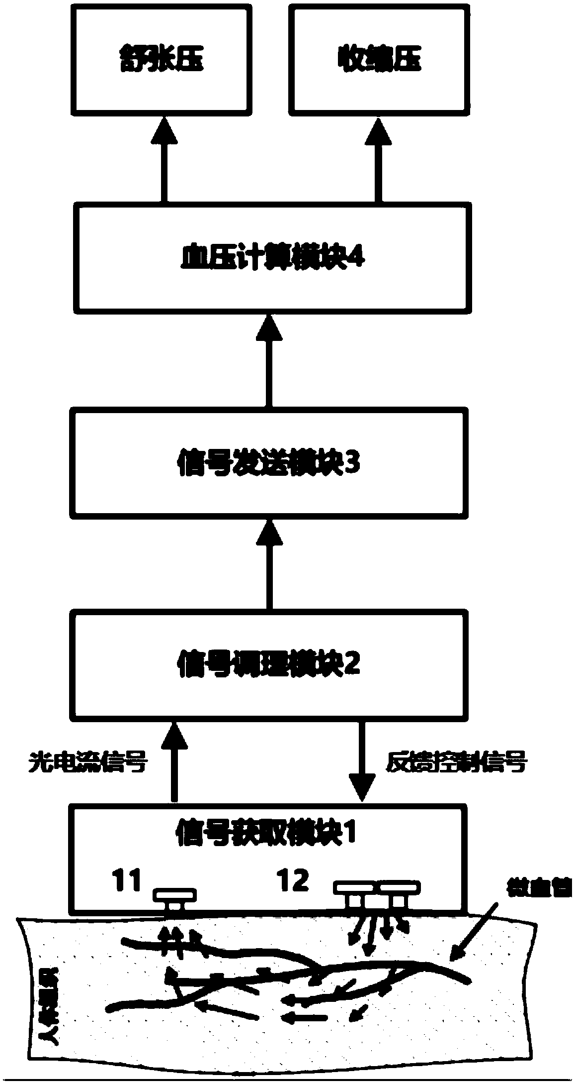
[0053] Please see first figure 1 , figure 1 It is a working schematic diagram of a real-time blood pressure monitoring device based on a single-channel PPG signal in this embodiment. As shown in the figure, a real-time blood pressure measurement device based on a single-channel PPG signal includes: a signal acquisition module 1, a signal conditioning module 2, and a signal transmission module. Module 3 and blood pressure calculation module 4. Wherein, the signal acquisition module 1 is used to detect the blood volume information in the microvessels of the human body, and utilizes light-emitting diodes (LEDs) to irradiate human tissue, and the light absorption intensity of human tissue can be determined by the Lambert-Beer law: A=lg(I / I 0 )=Kbc expression, where A is the absorbance, I is the outgoing light intensity, and I 0 is the incident light intensity; K is the molar absorption coefficient, c is the concentration of light-absorbing substances, and b is the thickness of t...


PUM


Abstract

The invention discloses a real-time blood pressure monitoring device based on a one-channel PPG signal. A signal acquisition module illuminates human body tissues and detects the intensity of the reflected light, and outputs a photocurrent signal; a signal modulation module modulates the photocurrent signal and feeds back and controls a light source emitter to obtain PPG voltage signals; a signalsending module samples the PPG voltage signals and sends the PPG voltage signals to a blood pressure calculation module; and the blood pressure calculation module performs filter pre-processing on thePPG voltage signals, and extracts characteristic values into a blood pressure calculation model for calculation to obtain real-time blood pressure and heart rate values. The real-time blood pressuremonitoring device is based on the real-time and continuity of the PPG signals, carries out all-weather blood pressure monitoring, reflects the diurnal variation of blood pressure, diagnoses early hypertension, assists in the identification of primary, secondary and complex hypertension, and has important significance in guiding rational medicine use. The real-time blood pressure monitoring devicehas obvious advantages in device power consumption, monitoring real-time performance and measurement accuracy.

Description

technical field [0001] The invention relates to the technical field of blood pressure monitoring, in particular to a real-time blood pressure monitoring device based on a single-channel photoplethysmography (photoplethysmography, PPG for short) signal. Background technique [0002] According to the 2016 World Health Organization report, approximately 17.7 million people die from cardiovascular diseases each year, accounting for 30% of the global death toll. In my country alone, the number of people who die from cardiovascular disease is as high as 3.5 million every year, that is, one person dies from cardiovascular disease every 10 seconds. Among them, high blood pressure is the primary risk factor for cardiovascular disease. Sustained high blood pressure can cause complications such as myocardial infarction, stroke, renal failure (uremia), aortic dissection, fundus disease, and peripheral vascular disease. Quality of life, severe cases are life-threatening. In my country,...

Claims


Application Information

Patent Timeline
Patent Type & Authority Applications(China)
IPC IPC(8): A61B5/021A61B5/00
CPCA61B5/021A61B5/7203A61B5/7207A61B5/7235A61B5/725
Inventor 王国兴连勇王敏谢青松
Owner SHANGHAI JIAO TONG UNIV
Why Eureka
Try Eureka