Manufacturing method of rotor

A manufacturing method and rotor technology, which can be used in the manufacture of motor generators, stator/rotor bodies, magnetic circuit rotating parts, etc., can solve the problems of difficulty in controlling the placement of adhesives, and prevent the placement of adhesives from becoming difficult. , The effect of improving insertability and preventing an increase in the number of processes

Active Publication Date: 2021-02-05
AISIN AW CO LTD
View PDF10 Cites 0 Cited by
  • Summary
  • Abstract
  • Description
  • Claims
  • Application Information

AI Technical Summary

Problems solved by technology

However, in this method, during press molding, the adhesive pressed by the mold may seep (enter) between the mold and the position where the permanent magnet should be in contact (the position where the adhesive should not be placed), or the adhesive may It seeps out of the mold from the gap between the mold and the permanent magnet, and it is difficult to control the placement position of the adhesive (adhesive placement position).
Therefore, in the permanent magnet fixing method (rotor manufacturing method) described in Japanese Patent Application Laid-Open No. 2007-151362, the adhesive is attached to positions other than the desired arrangement position (adhesive arrangement position). For example, after the magnet is inserted, the cured adhesive may overflow from the axial end face of the rotor core

Method used


Image

  • Manufacturing method of rotor
  • Manufacturing method of rotor
  • Manufacturing method of rotor

Examples


Embodiment Construction

[0030] Embodiments of the present invention will be described below based on the drawings.

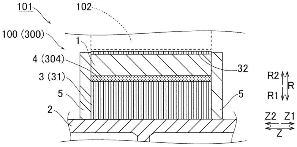
[0031] [Structure of the rotor of the first embodiment]

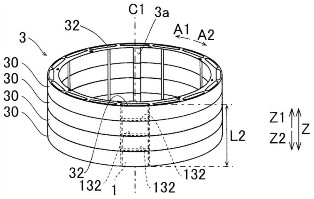
[0032] refer to Figure 1 to Figure 8 The structure of the rotor 100 of the first embodiment will be described.

[0033] In addition, in the specification of the present application, "rotating electric machine" is described as a concept including any one of a motor (electric motor), a generator (generator), and a motor generator that functions as both a motor and a generator as needed. For example, the rotary electric machine 101 is configured in the form of a traction motor used in a hybrid vehicle or an electric vehicle.

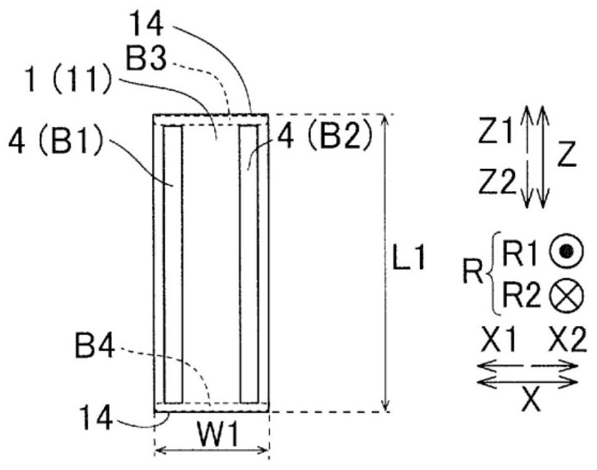
[0034] In addition, in the specification of this application, "rotor rotation axis direction" or "axial direction" refers to the rotation axis direction of the rotor 100 (along the axis C1 (refer to figure 2 ) direction; and figure 1 in the direction parallel to the Z-axis). In addition, "circumferenti...


PUM


Abstract

The manufacturing method of the rotor includes: the process of applying adhesive to the outer peripheral surface of the permanent magnet or the inner peripheral surface of the rotor core at the position where the adhesive is arranged; the process of drying the adhesive; The process of fixing the permanent magnets to the rotor core by expanding the contained expansion agent and curing the adhesive.

Description

technical field [0001] The invention relates to a method for manufacturing a rotor. Background technique [0002] Conventionally, a rotor manufacturing method is known in which a permanent magnet is inserted into a magnet hole portion of a rotor core. A method of manufacturing such a rotor is disclosed in JP 2007-151362 A. [0003] Japanese Patent Application Laid-Open No. 2007-151362 discloses a permanent magnet fixing method in which a permanent magnet is inserted and accommodated in a storage groove of a rotor core. For this permanent magnet fixing method, first, an adhesive sheet formed independently of the permanent magnet and formed in a sheet shape is attached to the surface of the permanent magnet, or a molten adhesive is dropped to arrange a Adhesives (or adhesive sheets) for foaming agents. In addition, an adhesive or an adhesive sheet is used as an "adhesive member". Thereafter, in order to position and fix the bonded material on the permanent magnet, the bond...

Claims


Application Information

Patent Timeline
Patent Type & Authority Patents(China)
IPC IPC(8): H02K1/27H02K15/02
CPCH02K1/276H02K15/03H02K15/12H02K1/274H02K1/28Y02T10/64
Inventor 牛田英晴松原哲也高桥哲也片山慎也
Owner AISIN AW CO LTD
Why Eureka
Try Eureka