A 3D printing laser galvanometer level detection method

A level detection, laser galvanometer technology, applied in the field of 3D printing, can solve problems such as uneven installation of galvanometers and poor printing effects, avoid manual testing, reduce labor costs and testing time, and improve printing yield and work efficiency Effect

Active Publication Date: 2021-04-06
HANS LASER TECH IND GRP CO LTD +1
View PDF6 Cites 0 Cited by
  • Summary
  • Abstract
  • Description
  • Claims
  • Application Information

AI Technical Summary

Problems solved by technology

[0003] The technical problem to be solved by the present invention is to provide a method for detecting the level of the 3D printing laser vibrating mirror, which aims to solve the problem that the vibrating mirror is not installed horizontally, resulting in poor printing effect

Method used


Image

  • A 3D printing laser galvanometer level detection method
  • A 3D printing laser galvanometer level detection method
  • A 3D printing laser galvanometer level detection method

Examples


Embodiment Construction

[0021] Now in conjunction with the accompanying drawings, the preferred embodiments of the present invention will be described in detail.

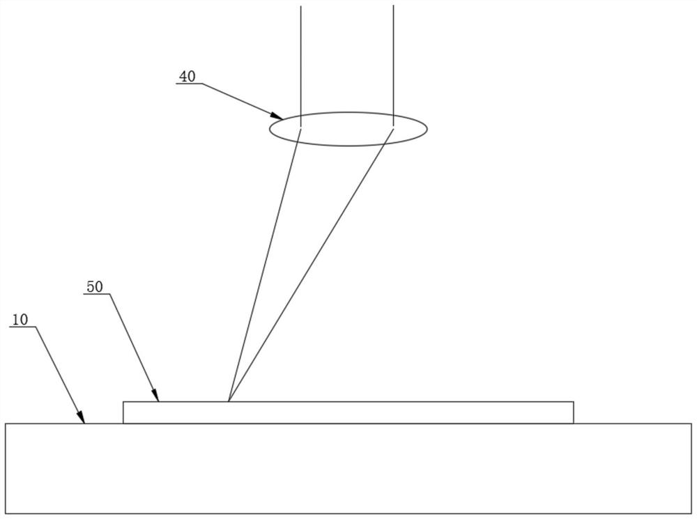
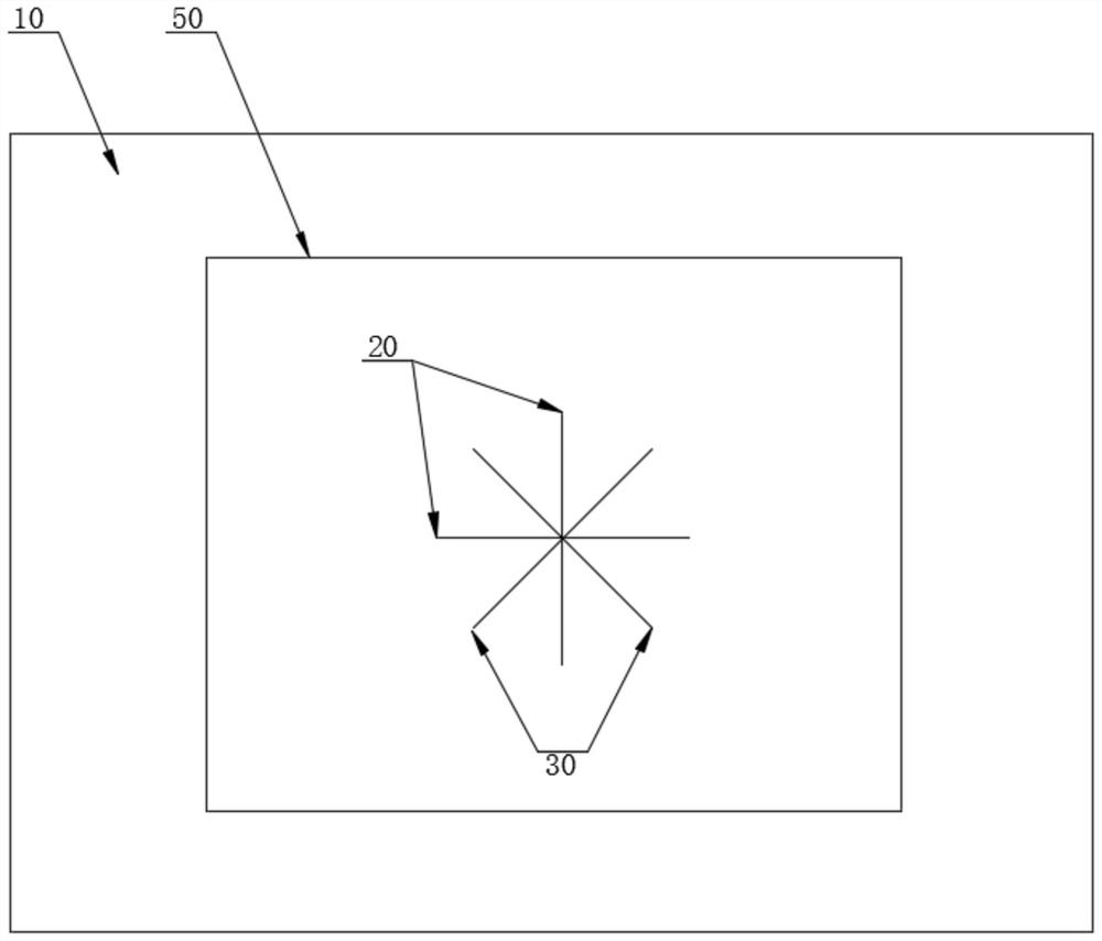
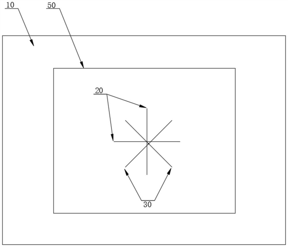
[0022] Such as figure 1 As shown, the present invention provides a method for detecting the level of a 3D printing laser vibrating mirror. The method is based on a powder-spreading 3D laser printing machine, and includes the following steps: S1, confirming that the printing platform 10 is in a horizontal state; S2, establishing cross coordinates, and controlling the laser Print the first cross-shaped track 20 on the printing platform 10; S3, control the cross coordinates to rotate 0-90 °, control the laser to continue printing the second cross-shaped track 30 on the printing platform 10; S4, observe the first cross-shaped track 20 and Whether the intersection points of the second cross-shaped track 30 coincide is to determine whether the vibrating mirror 40 is installed horizontally. Such as figure 2 As shown, when the intersection of t...


PUM


Abstract

The invention relates to a method for detecting the level of a 3D printing laser vibrating mirror. After confirming that the printing platform is in a horizontal state, establish a cross coordinate, control the laser to print the first cross-shaped track on the printing platform, and then control the rotation of the cross coordinate to 0‑90° to control The laser continues to print the second cross-shaped track on the printing platform, and finally observe whether the intersection of the first cross-shaped track and the second cross-shaped track coincides to judge whether the vibrating mirror is installed horizontally. When the intersection of the first cross-shaped track and the second cross-shaped track coincides, the vibrating mirror is installed horizontally; when the intersection of the first cross-shaped track and the second cross-shaped track does not coincide, the vibrating mirror is not installed horizontally, This can achieve the purpose of quickly and automatically detecting whether the galvanometer is installed horizontally, thereby avoiding manual testing, greatly reducing labor costs and testing time, and improving printing yield and work efficiency.

Description

technical field [0001] The invention relates to the technical field of 3D printing, in particular to a method for detecting the level of a 3D printing laser vibrating mirror. Background technique [0002] Powder-spreading 3D printing uses a focused low-power-density laser beam to irradiate metal powder to rapidly sinter the irradiated metal powder. At the same time, by controlling the oxygen content, air pressure, and temperature, the metal powder is sintered and printed layer by layer. Finally, 3D printing is realized. This process will affect the printing effect of the workpiece because the galvanometer is not installed horizontally and is not printed at the specified position. If it is not at the specified position, the specified position will not be reached during printing, which will affect the final effect of the printed workpiece. Contents of the invention [0003] The technical problem to be solved by the present invention is to provide a method for detecting the ...

Claims


Application Information

Patent Timeline
Patent Type & Authority Patents(China)
IPC IPC(8): G01C9/00
CPCG01C9/00
Inventor 雷祖全何建宏陈少煌向水平陈根余陈焱高云峰
Owner HANS LASER TECH IND GRP CO LTD
Why Eureka
Try Eureka