
A fault zone activity monitoring method, exploration method and device
- Summary
- Abstract
- Description
- Claims
- Application Information
AI Technical Summary
Problems solved by technology
Method used
Image

Examples
Embodiment 1
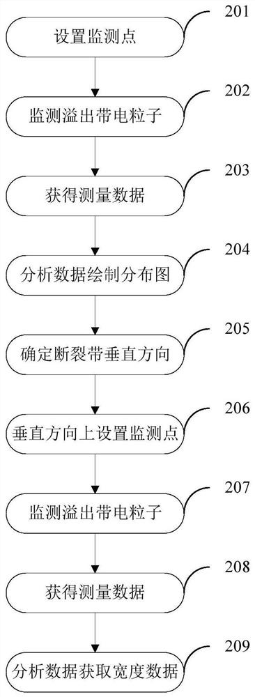
[0035] Please refer to figure 2 , is a flow chart of a fault zone exploration method in an embodiment. This application discloses a method for exploration of fault zones, including:
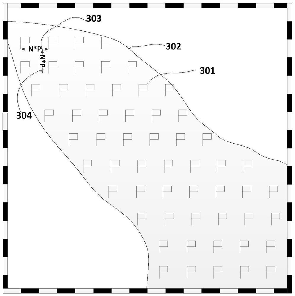
[0036] Step 201, setting multiple monitoring points in the pre-measured target area according to the monitoring accuracy. that is, image 3 As shown, it is a schematic diagram of setting monitoring points for the target area in an embodiment. The range delineated by the curve 302 is the pre-measured target area, and the marking lines 303 and 304 are the length and width of the positioning accuracy P (in meters). A plurality of monitoring points 301 are set in the pre-measured target area according to the monitoring accuracy.
[0037] Step 202, monitor the charged particles overflowing from the ground surface at the monitoring point. It is the characteristic of charged particles spilled from the ground surface by the application of charged particle monitoring devices. The charged particle mo...
Embodiment 2
[0055] Please refer to Figure 7 , is a flow chart of a fault zone activity monitoring method in another embodiment. The application discloses a method for monitoring the activity of a fault zone, including:
[0056] Step 701, setting a plurality of width monitoring points in the vertical direction of known fault zone distribution. Draw the horizontal direction and vertical direction of the fault zone according to the schematic diagram of the distribution of the known fault zone. Due to the structural characteristics of the fault zone, it is distributed in a band shape, and the extension direction of the fault zone to both sides is defined as the horizontal direction of the fault zone. The horizontal direction and the vertical direction are the vertical direction of the fault zone.
[0057] Step 702, monitor the charged particles overflowing from the ground surface at the width monitoring point. It is the characteristic of charged particles spilled from the ground surface b...
Embodiment 3
[0063] Such as Figure 8 Shown is a structural schematic diagram of a fault zone exploration device in another embodiment. The present application discloses a fault zone detection device including a permanent magnetic core 804 , a coil 803 and a signal acquisition circuit 805 . The permanent magnet core 804 is magnetic, and the coil 803 is wound around the periphery of the permanent magnet core 804 . Both ends of the coil 803 are respectively connected to the input terminals of the signal acquisition circuit 805 . An induction signal is generated when the inner space of the coil 803 is passed through by the surface overflow charged particles 801 . The signal acquisition circuit 805 is used to acquire the induced electrical signal generated by the coil 803 . The function of the permanent magnetic core 804 is to increase the magnetic permeability of the coil 803 , so that the signal acquisition circuit 805 can obtain the induced electrical signal in the coil 803 more easily. ...
PUM
 Abstract
Description
Claims
Application Information