Novel low-temperature air distributing valve structure

A low-temperature valve and gas distribution valve technology, which is applied in the field of new low-temperature gas distribution valve structure, can solve problems such as low-temperature system influence, worn valves, and low-temperature gas pollution, and achieve good sealing and heat insulation performance, solve gas distribution problems, and good sealing effect of effect

Active Publication Date: 2018-12-25
TECHNICAL INST OF PHYSICS & CHEMISTRY - CHINESE ACAD OF SCI
View PDF9 Cites 0 Cited by
  • Summary
  • Abstract
  • Description
  • Claims
  • Application Information

AI Technical Summary

Problems solved by technology

[0004] Existing low-temperature mechanical valves often have the problem of wear and tear during operation and the problem of air passage before and after the valve or gas passage between the internal air passage of the valve and the outside world. These problems seriously affect the gas distribution efficiency of the low-temperature mechanical valve, which directly affects the low-temperature System stability
At the same time, under high-frequency movement, debris and other impurities generated by the cryogenic mechanical valve due to wear and tear will be mixed into the gas flow path, which will pollute the cryogenic gas and have a huge impact on the entire cryogenic system.

Method used


Image

  • Novel low-temperature air distributing valve structure
  • Novel low-temperature air distributing valve structure

Examples


Embodiment Construction

[0024] The present invention will be further described in detail below in conjunction with the accompanying drawings, so that those skilled in the art can implement it with reference to the description.

[0025] It should be noted that, in the description of the present invention, the terms "horizontal", "vertical", "upper", "lower", "front", "rear", "left", "right", "vertical", The orientation or positional relationship indicated by "horizontal", "top", "bottom", "inner", "outer", etc. is based on the orientation or positional relationship shown in the drawings, and is only for the convenience of describing the present invention and simplifying the description, and It is not to indicate or imply that the device or element referred to must have a particular orientation, be constructed in a particular orientation, or operate in a particular orientation, and thus should not be construed as limiting the invention.

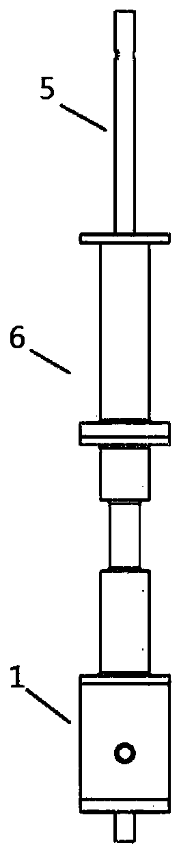
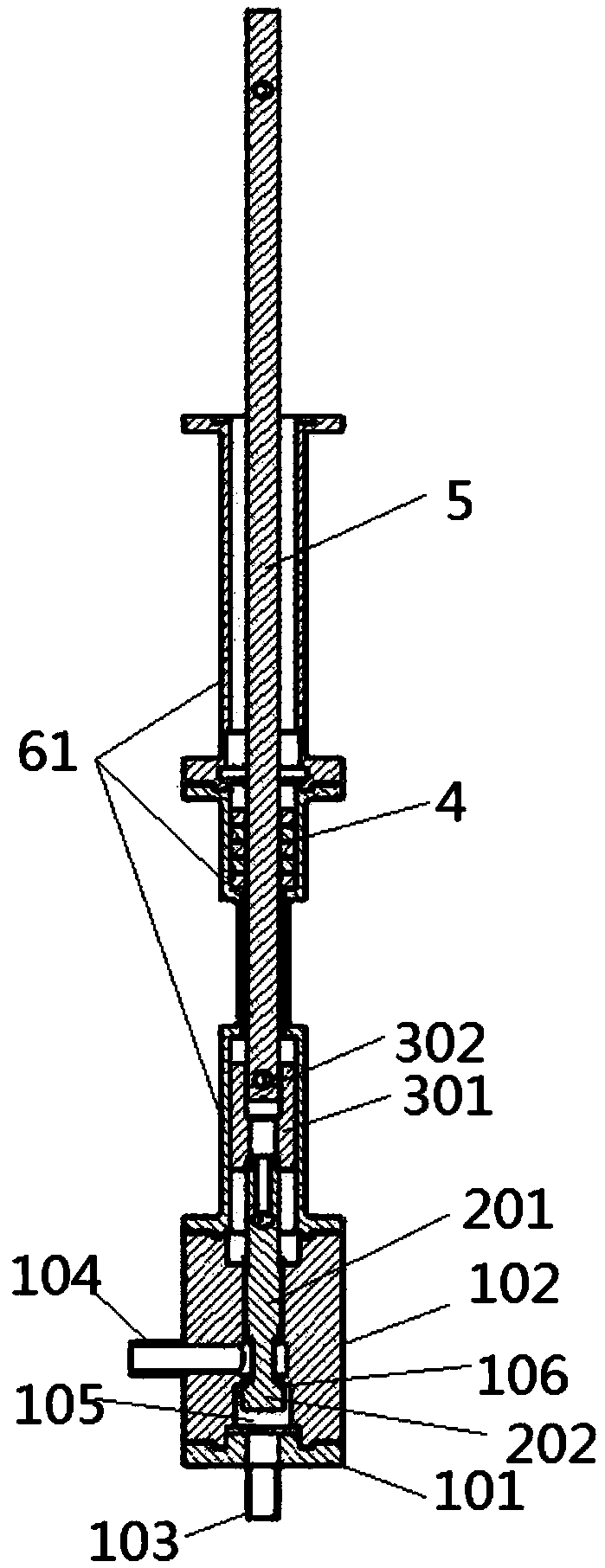
[0026] Such as Figure 1~2 As shown, the structure of the new l...


PUM


Abstract

The invention discloses a novel low-temperature air distributing valve structure. The novel low-temperature air distributing valve structure comprises a low-temperature valve seat assembly and an aircylinder assembly. A low-temperature valve core assembly capable of moving up and down is coaxially arranged in the low-temperature valve seat assembly. The air cylinder assembly is coaxially arrangedabove the low-temperature valve seat assembly, and a shaft sleeve is coaxially sleeved with the air cylinder assembly and can move up and down along the axis of the air cylinder assembly. A valve rodis coaxially sleeved with the air cylinder assembly and located above the shaft sleeve. The lower end of the valve rod is connected with the low-temperature valve core assembly through the shaft sleeve. The position between the valve rod and the air cylinder assembly is filled with a heat insulating assembly. The valve rod moves up and down to drive the low-temperature valve core assembly to moveso as to achieve opening and closing of the low-temperature valve seat assembly. According to the novel low-temperature air distributing valve structure, smoothness of high-frequency motion is achieved through the motion form that the valve rod drives the low-temperature valve core assembly to move in the axial direction of the low-temperature valve seat assembly, transmission of high valve braking force under high frequency is ensured by adopting shaft sleeve connection, through the heat insulating assembly arranged between the valve rod and the air cylinder assembly in a filling mode, the good sealing performance and good heat insulating performance of a valve are achieved, and the air distributing efficiency of the valve is improved.

Description

technical field [0001] The invention relates to the technical field of low temperature refrigeration. More specifically, the present invention relates to a novel low temperature gas distribution valve structure. Background technique [0002] In recent years, research in the field of cryogenics has continued to deepen, and related low-temperature experiments have been carried out in turn. The demand for cryogenic equipment is increasing in current research, and most of the cryogenic equipment and systems are inseparable from cryogenic gases. Therefore, the requirements for gas valves in the cryogenic field continue to increase, and achieving efficient gas distribution has become a basic requirement for cryogenic valves. [0003] Cryogenic valves are often used in the form of pneumatic valves, solenoid valves, and mechanical valves. Pneumatic valves are difficult to seal at low temperatures, and heat leakage and air leakage are unavoidable problems. The solenoid valve itsel...

Claims


Application Information

Patent Timeline
Patent Type & Authority Applications(China)
IPC IPC(8): F16K1/00F16K31/122
CPCF16K1/00F16K31/122
Inventor 龚领会王立智贾启明李正宇张梅梅朱伟平
Owner TECHNICAL INST OF PHYSICS & CHEMISTRY - CHINESE ACAD OF SCI
Why Eureka
Try Eureka