
Clamp type refractory material mounting clip and using method thereof
A technology for installation clips and clamping teeth, which is applied to furnaces, lighting and heating equipment, lining repairs, etc., can solve problems such as installation difficulties, falling off, friction fatigue, etc., to increase production energy consumption, reduce operating time, and reduce The effect of labor intensity
- Summary
- Abstract
- Description
- Claims
- Application Information
AI Technical Summary
Problems solved by technology
Method used
Image

Examples
Embodiment 1
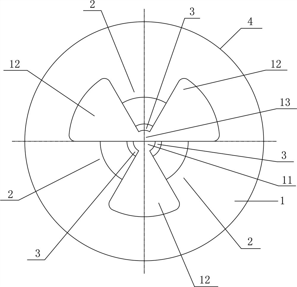
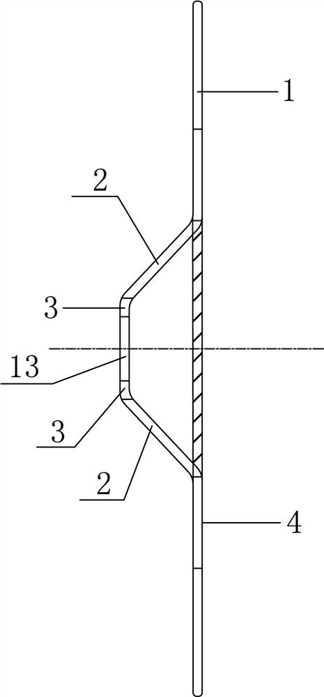
[0032] A locking type refractory mounting clip, including a circular bottom plate 1, a support plate 2 and locking teeth 3, such as figure 1 and figure 2 As shown, the specific structure is:
[0033] The center of the base plate 1 is provided with a circular hole 11 concentric with the base plate 1. At least three fan-shaped blocks are punched out on the base plate 1 to form at least three fan-shaped holes 12. The centers of the fan-shaped holes 12 coincide with the centers of the base plate 1. Evenly distributed around the bottom plate 1; the triangular block between two adjacent fan-shaped holes 12 becomes the support plate 2, and each support plate 2 is inclined in the same direction, so that the envelope of the outer surface of each support plate 2 forms a circular truncated shape, The inner end of the support plate 2 is provided with locking teeth 3 , and the inner end of each locking tooth 3 is enveloped to form a small circular hole 13 concentric with the bottom plate...
PUM
 Abstract
Description
Claims
Application Information