
An angle-adjustable grounding wire clamp

A technology for grounding clamps and angle adjustment, which is applied in the direction of connection, conductive connection, electrical connection seat, etc., and can solve problems such as low operating efficiency, insufficient safety distance, and poor angle

Pending Publication Date: 2019-01-15
GUANGDONG POWER GRID CO LTD +1
View PDF0 Cites 0 Cited by
  • Summary
  • Abstract
  • Description
  • Claims
  • Application Information

AI Technical Summary

Problems solved by technology

[0002] The conventional 10kV adjustable-angle grounding clamp is only suitable for the installation of the grounding wire in the horizontal wiring mode. For the line lead-off device, the vertical lead-down wiring method is used. When installing the grounding wire, the vertical adjustable-angle grounding clamp and the vertical When the wires are connected together, there is an angle difference, which makes the safety distance between the operator and the exposed live line insufficient when installing the grounding wire, the work efficiency is low, and the wires are broken.

Method used


Image

  • An angle-adjustable grounding wire clamp
  • An angle-adjustable grounding wire clamp

Examples


Embodiment Construction

[0016] The following will clearly and completely describe the technical solutions in the embodiments of the present invention with reference to the accompanying drawings in the embodiments of the present invention. Obviously, the described embodiments are only part of the embodiments of the present invention, not all of them. Based on the embodiments of the present invention, all other embodiments obtained by persons of ordinary skill in the art without creative efforts fall within the protection scope of the present invention.

[0017] It should be noted that if there is a directional indication (such as up, down, left, right, front, back...) in the embodiment of the present invention, the directional indication is only used to explain the position in a certain posture (as shown in the accompanying drawing). If the specific posture changes, the directional indication will also change accordingly.

[0018] In addition, if there are descriptions involving "first", "second" and ...


PUM

PropertyMeasurementUnit
Radianaaaaaaaaaa

Abstract

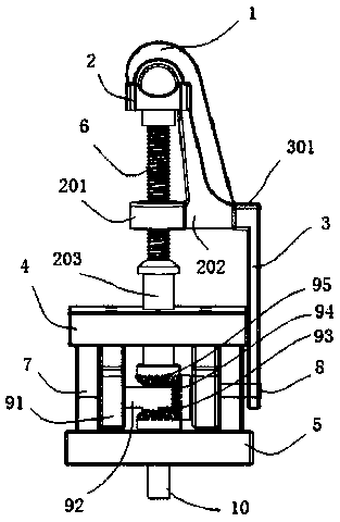
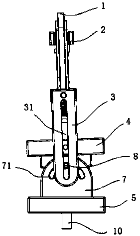
The invention discloses an angle-adjustable grounding wire clamp, wherein a downward concave shape of an upper clamp head and an upward concave shape of a lower clamp head are mutually matched to forma connecting clamp hole, a bottom end of the lower clamp head is fixedly connected with one end of an adjusting screw rod, and the other end of the adjusting screw rod passes through and is connectedwith an upper support plate; An end portion of the upper chuck extending downward is fixedly connected with the positioning plate; The two sides of the bottom surface of the upper support plate are respectively provided with sliding rails, two adjusting fixing plates are fixed on the two sides of the lower support plate, and the top end of the adjusting fixing plate is provided with an arc surface for cooperating with the sliding rails; The transmission assembly is positioned between the upper support plate and the lower support plate; The positioning plate extends downward to the outside ofthe adjustment fixing plate, the downward extending portion of the positioning plate is provided with a finite position hole, the top of the adjustment fixing plate is provided with an arc-shaped through hole along the circumferential direction of the arc-shaped surface, and the adjustment bolt passes through the arc-shaped through hole and the limit hole and is fixed by nuts. The angle-adjustablegrounding wire clamp adjusts the arc surface of the fixing plate and the slide rail of the upper support plate to be matched and connected, adjusts the grounding wire clamp to the required angle, andthen fixes the grounding wire clamp by adjusting bolts and nuts.

Description

technical field [0001] The invention relates to the field of electric appliances, in particular to an angle-adjustable grounding clamp. Background technique [0002] The conventional 10kV adjustable-angle grounding clamp is only suitable for the installation of the grounding line in the horizontal wiring mode. For the line lead-off device, the vertical lead-down wiring method is used. When installing the grounding wire, the vertical adjustable-angle grounding clamp and the vertical When the wires are connected together, there is an angle difference, which makes the safety distance between the operator and the exposed live line insufficient when installing the ground wire, the work efficiency is low, and the wires are broken. Contents of the invention [0003] The main purpose of the present invention is to propose an angle-adjustable grounding clamp, aiming at overcoming the above problems. [0004] In order to achieve the above object, the present invention proposes an a...

Claims


Application Information

Patent Timeline
IPC IPC(8): H01R11/26H01R4/36
CPCH01R4/366H01R11/26
Inventor 吴锦秋
Owner GUANGDONG POWER GRID CO LTD
Learn More