Magnetic conductive plate for positioning detachable transformer

A technology of magnetic conductive plate and transformer, applied in the direction of transformer, transformer/inductor magnetic core, transformer/inductor components, etc., can solve the problems of complex equipment, low reliability, foreign object interference, etc., and achieve low cost and reliability. The effect of high sex and high discrimination

Active Publication Date: 2019-03-01
NARI TECH CO LTD +2
View PDF7 Cites 0 Cited by
  • Summary
  • Abstract
  • Description
  • Claims
  • Application Information

AI Technical Summary

Problems solved by technology

However, because the limit switch is easily touched by other foreign objects, misjudgment may occur, and multiple limit switches will cause high cost and low reliability.
In addition, through microwave, laser and other methods, there are problems such as being easily disturbed by foreign objects, and the equipment is complex and easy to damage.

Method used


Image

  • Magnetic conductive plate for positioning detachable transformer
  • Magnetic conductive plate for positioning detachable transformer
  • Magnetic conductive plate for positioning detachable transformer

Examples


example 1

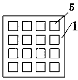
[0028] Example 1: If Figure 4 with 5 As shown, the coil 3 wound on the magnetic conductor 2 includes a row coil 32 and a column coil 31, the row coil 32 is located above, the column coil 31 is located below, N1+N2 electromotive force detection circuits 6, and the electromotive force detection circuit 6 adopts voltage Or the current sensor, the coils 31 of 2 columns of magnetizers in the same row are connected in series in sequence, and then connected with an electromotive force detection circuit 6, and the coils 32 of 2 rows of magnetizers in the same row are connected in series in sequence, and then connected with an electromotive force detection circuit 6.

[0029] The working mode is: when the separable transformer generates an alternating magnetic field, an alternating magnetic flux will be generated on the approaching or contacting magnetic conductor 2, and the row coil 32 and the column coil 31 will generate an induced electromotive force, which will generate a voltage ...

example 2

[0030] Example 2: If Image 6 As shown, the coil 3 wound on the magnetizer 2 can be a group, N1+N2 electromotive force detection circuits 6, the electromotive force detection circuit 6 adopts a voltage or current sensor, and the coils 3 of the magnetizer 2 located in the same column / row are connected in series. All the series branches of the diode 7 are connected to the electromotive force detection circuit 6 in parallel, and the conduction directions of the diodes 7 connected in series with the coils 3 of the magnetizer 2 located in the same column / row are consistent.

[0031] The working mode is: when the separable transformer generates an alternating magnetic field, it will generate alternating magnetic flux on the magnetic conductor 2 that is close to or in contact with it, and the coil 3 will generate an induced electromotive force, and when the direction of the current generated by the induced electromotive force is consistent with the conduction direction of the diode 7 ...


PUM


Abstract

The invention discloses a magnetic conductive plate for positioning a detachable transformer. The magnetic conductive plate comprises a supporting plate and a plurality of magnetic conductive bodies;a plurality of through holes are formed in the supporting plate, the coils are wound around the magnetic conductive bodies and connected with an electromotive force detecting circuit, and the magneticconductive bodies with the wound coils are embedded and fixed into the through holes. During charging, alternating flux is generated on the magnetic conductive bodies abutting against the detachabletransformer in a attached mode, alternating electromotive force is generated in the corresponding coils, which magnetic conductive body coil generates the alternating electromotive force is detected through the electromotive force detecting circuit, and thus the position of the detachable transformer abutting against the detachable transformer in the attached mode can be judged; due to the fact that a magnetic field generated by the detachable transformer is sensed, the identification discrimination degree is high, and the magnetic conductive plate is not prone to being influenced by foreign matter and other disturbance; and the weak link that mechanical parts and optical parts are prone to being consumed and damaged is avoided, thus reliability is high, and the cost is low.

Description

technical field [0001] The invention relates to a magnetically conductive plate for positioning a separable transformer, belonging to the technical field of electric vehicle charging. Background technique [0002] The high-power and high-efficiency charging requirements of electric vehicle charging can be realized through the separable transformer mode, using the structure of the secondary side of the electric vehicle side separable transformer, the ground oriented magnetic guide plate, and the ground separable transformer primary side. The secondary side of the separable transformer of the electric vehicle automatically descends to the directional magnetic guide plate after parking, and the primary side of the separable transformer is aligned with the secondary side of the separable transformer to generate magnetic flux, which is coupled with the secondary side of the separable transformer through the directional magnetic guide plate , transfer electric energy. Compared wi...

Claims


Application Information

Patent Timeline
Patent Type & Authority Applications(China)
IPC IPC(8): B60L53/12B60L53/38H01F27/00H01F27/24H01F38/14
CPCH01F27/00H01F27/24H01F38/14Y02T90/14
Inventor 于春来骆健朱金大黄珺胡远婷张洪达朱学成
Owner NARI TECH CO LTD
Why Eureka
Try Eureka