
Sealing structure and jar with sealing structure
A technology of sealing structure and jar, which is applied to engine sealing, wellbore/well parts, engine components, etc., can solve the problems of loss of sealing effect and equipment damage, etc., and achieve reasonable design of sealing structure, easy replacement and excellent performance Effect
- Summary
- Abstract
- Description
- Claims
- Application Information
AI Technical Summary
Problems solved by technology
Method used
Image

Examples
Embodiment 1
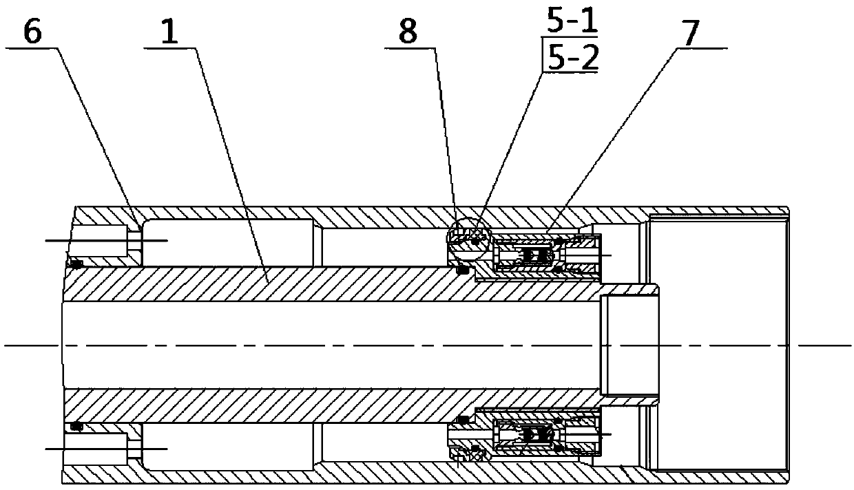
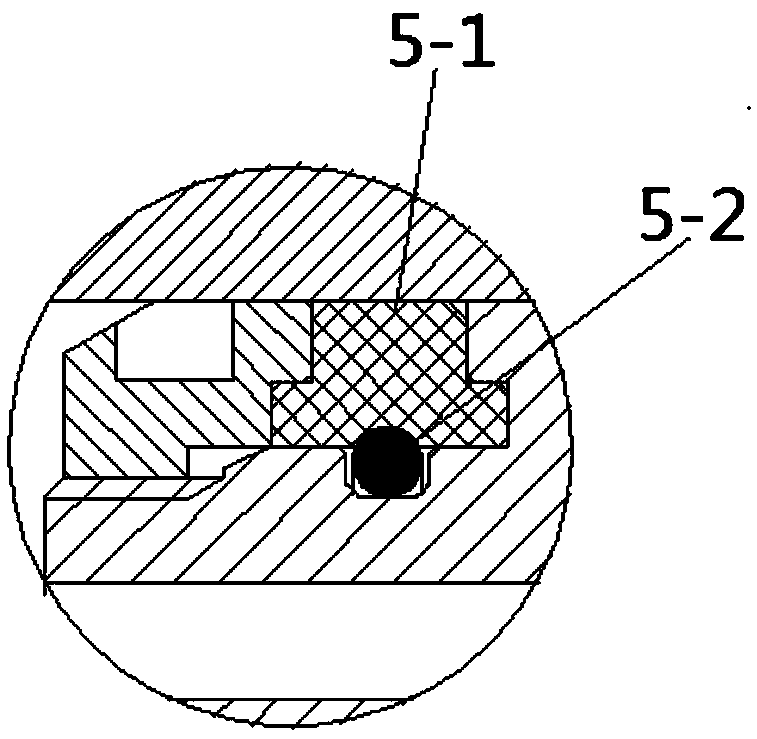
[0040] Such as figure 2 , when the shock shaft 1 is pulled up, the pressure in the high-pressure chamber rises, the hydraulic oil pushes the sealing piston 4 to move, and the sealing piston 4 pushes the push sleeve 3 to move. At this time, the push sleeve 3 is subjected to the elastic member 2 in the shock shell 6 Active force, so the greater the force of the elastic member 2, the higher the pressure in the high-pressure chamber. When the shock shaft 1 moves to a certain position, the pressure in the high-pressure chamber is released, and there is a process of pressure balance on both sides, which produces a sudden change in pressure. The vibration shaft 1 is connected with the vibration hammer 7, and the middle is sealed by a second O-ring. The shock shaft 1 and the shock housing 7 are sealed by a first O-ring. The vibration hammer 7 and the vibration shell 6 are sealed by a combined sealing ring, and the combined sealing ring is arranged between the vibration hammer 7 and...
Embodiment 2
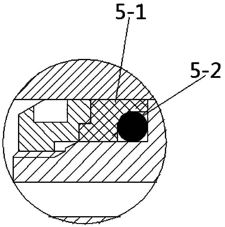
[0043] Such as image 3, when the shock shaft 1 is pulled up, the pressure in the high-pressure chamber rises, the hydraulic oil pushes the sealing piston 4 to move, and the sealing piston 4 pushes the push sleeve 3 to move. At this time, the push sleeve 3 is subjected to the elastic member 2 in the shock shell 6 Active force, so the greater the force of the elastic member 2, the higher the pressure in the high-pressure chamber. When the shock shaft 1 moves to a certain position, the pressure in the high-pressure chamber is released, and there is a process of pressure balance on both sides, which produces a sudden change in pressure. The vibration shaft 1 is connected with the vibration hammer 7, and the middle is sealed by a second O-ring. The shock shaft 1 and the shock housing 7 are sealed by a first O-ring. The vibration hammer 7 and the vibration shell 6 are sealed by a combined sealing ring, and the combined sealing ring is arranged between the vibration hammer 7 and t...
Embodiment 3
[0046] Such as Figure 4 , when the shock shaft 1 is pulled up, the pressure in the high-pressure chamber rises, the hydraulic oil pushes the sealing piston 4 to move, and the sealing piston 4 pushes the push sleeve 3 to move. At this time, the push sleeve 3 is subjected to the elastic member 2 in the shock shell 6 Active force, so the greater the force of the elastic member 2, the higher the pressure in the high-pressure chamber. When the shock shaft 1 moves to a certain position, the pressure in the high-pressure chamber is released, and there is a process of pressure balance on both sides, which produces a sudden change in pressure. The vibration shaft 1 is connected with the vibration hammer 7, and the middle is sealed by a second O-ring. The shock shaft 1 and the shock housing 7 are sealed by a first O-ring. The vibration hammer 7 and the vibration shell 6 are sealed by a combined sealing ring, and the combined sealing ring is arranged between the vibration hammer 7 and...
PUM
 Abstract
Description
Claims
Application Information