Method for Controlling Speed ​​Fluctuation of Single Rotor Compressor

A single-rotor compressor and speed fluctuation technology, which is applied in the control system, motor control, torque ripple control, etc., can solve the problems of compressor speed fluctuation and the effect of speed fluctuation suppression are not ideal, so as to achieve direct speed fluctuation and improve fluctuation Inhibition effect, effect of improving stability

CN109698645BActive Publication Date: 2021-10-29QINGDAO HAIER AIR CONDITIONER GENERAL CORP LTD +1
6 Cites 0 Cited by

Patent Information

Authority / Receiving Office
CN · China
Patent Type
Patents(China)
Current Assignee / Owner
Publication Date
2021-10-29

Smart Images

  • Figure 1
    Figure 1
  • Figure 2
    Figure 2
  • Figure 3
    Figure 3
Patent Text Reader

Abstract

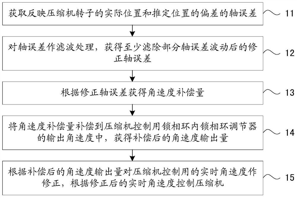
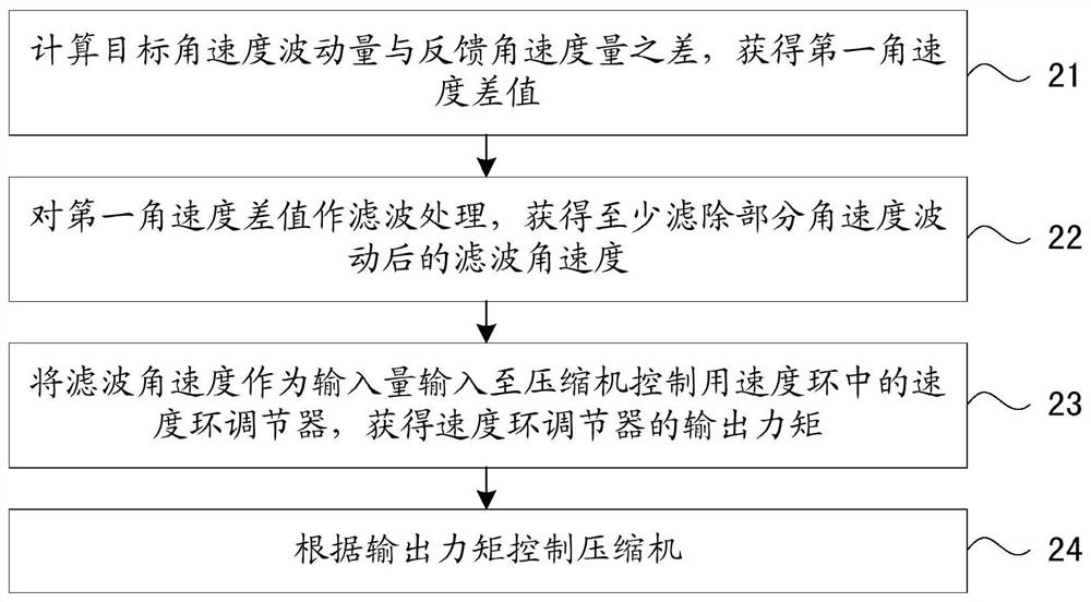
The invention discloses a method for controlling the rotation speed fluctuation of a single-rotor compressor, including the process of controlling the compressor according to the real-time angular velocity and torque; the process of controlling the compressor according to the real-time angular velocity includes: filtering the shaft error to obtain angular velocity compensation amount; compensate the angular velocity compensation amount to the output angular velocity of the phase-locked loop regulator to obtain the compensated angular velocity output; correct the real-time angular velocity according to the compensated angular velocity output, and control the compressor according to the corrected real-time angular velocity The process of controlling the compressor according to the torque includes: calculating the difference between the target angular velocity fluctuation and the feedback angular velocity to obtain the first angular velocity difference; filtering the first angular velocity difference to obtain the filtered angular velocity; Input to the speed loop regulator to obtain the output torque; control the compressor according to the output torque. By applying the present invention, the effectiveness of suppressing the fluctuation of the rotational speed of the compressor can be improved.
Need to check novelty before this filing date? Find Prior Art

Description

technical field

[0001] The invention belongs to the technical field of motor control, in particular relates to compressor control technology, and more specifically relates to a method for controlling fluctuations in the rotational speed of a single-rotor compressor. Background technique

[0002] When the single-rotor compressor used in the air conditioner is running, it is affected by the working principle and control technology of the air conditioner as a load, which makes the load torque of the compressor extremely unstable, which easily causes large speed fluctuations, and the compressor does not run smoothly. smooth. The unstable operation of the compressor will lead to unstable operation of the entire air conditioner system, causing various adverse effects. Moreover, the unstable operation will also generate relatively large operating noise, which cannot meet the requirements of relevant noise standards and affect the comfort of the air conditioner. This phenomenon is...

Examples

Embodiment Construction

[0030] In order to make the object, technical solution and advantages of the present invention clearer, the present invention will be further described in detail below in conjunction with the accompanying drawings and embodiments.

[0031] figure 1 and figure 2 Partial flow charts of an embodiment of the method for controlling the fluctuation of the rotational speed of the single-rotor compressor based on the present invention are respectively shown. Specifically, the method for speed fluctuation control in this embodiment includes two processes: one is the process of controlling the compressor according to the real-time angular velocity, the flow chart is as follows figure 1 Shown; one is the process of controlling the compressor according to the torque, the flow chart is as follows figure 2 shown. The following is based on figure 1 and figure 2 , while combining image 3 A control block diagram is shown, respectively describing the concrete realization of these two ...