

Multi-band built-in antenna
A built-in antenna, multi-band technology, applied in the direction of antenna, antenna grounding device, antenna grounding switch structure connection, etc., can solve problems such as large space, and achieve the effect of increasing flexibility, ensuring reliable work, and improving reliability and stability.
- Summary
- Abstract
- Description
- Claims
- Application Information
AI Technical Summary
Problems solved by technology
Method used
Image

Examples
Embodiment Construction
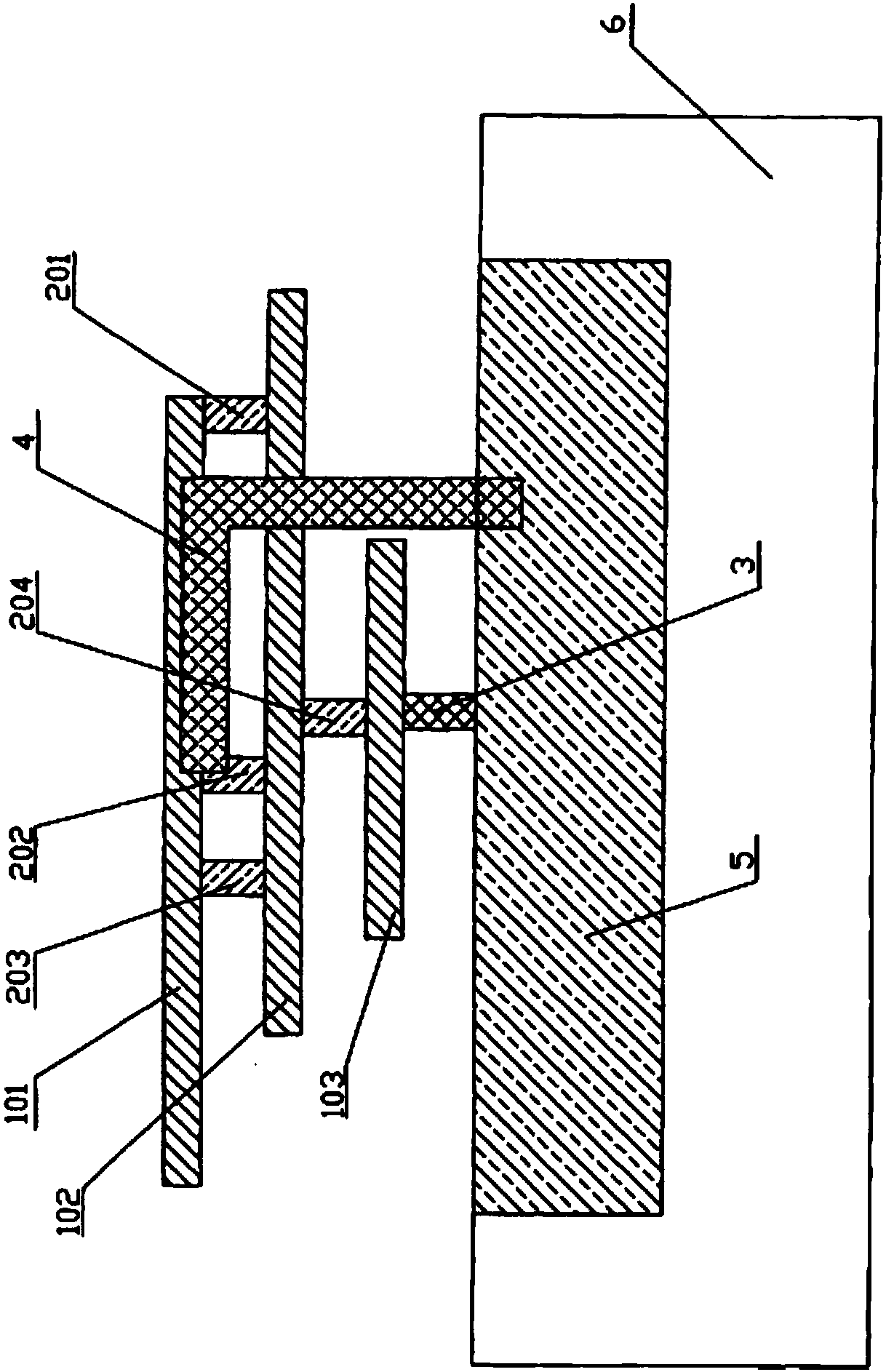
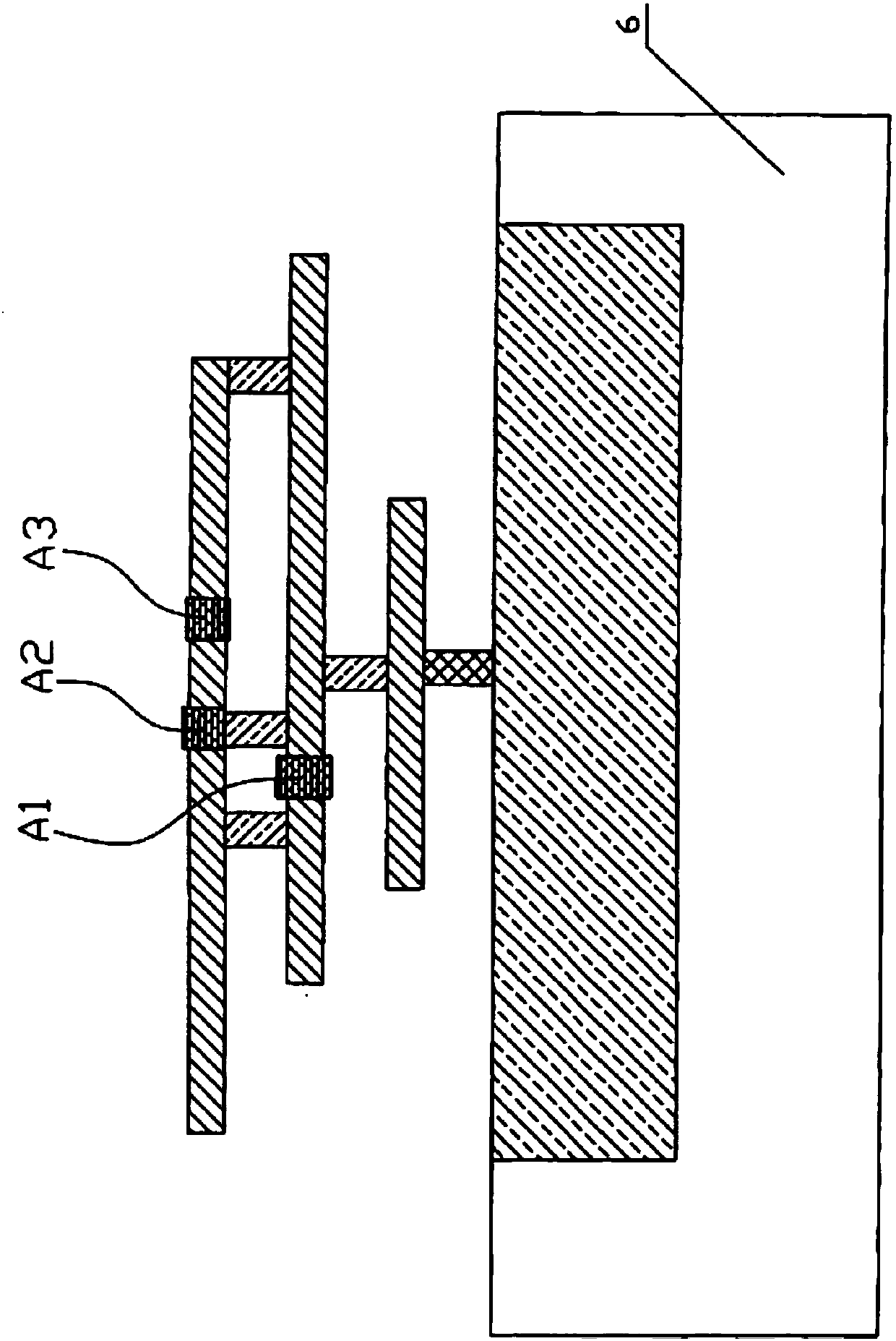
[0031] see figure 1 , the present invention relates to a multi-band built-in antenna, comprising a horizontal branch, a vertical branch, a metal feeding strip 3, a grounding metal strip 4, a substrate ground plane 5 and a substrate 6, and the substrate ground plane 5 is a metal in the substrate 6 layer, used to simulate the actual working ground plane of the antenna; the horizontal branch includes a horizontal branch one 101, a horizontal branch two 102 and a horizontal branch three 103, and the vertical branch includes a vertical branch one 201, a vertical branch two 202, a vertical branch Branch three 203 and vertical branch four 204, the horizontal branch one 101 and horizontal branch two 102 are connected by vertical branch one 201, vertical branch two 202 and vertical branch three 203, and the horizontal branch two 102 and horizontal branch three 103 are connected by The vertical branch four 204 is connected, the horizontal branch three 103 is connected to the substrate g...
PUM
| Property | Measurement | Unit |
|---|---|---|
| Thickness | aaaaa | aaaaa |
Abstract
Description
Claims
Application Information