
storm windows
A window and window frame technology, applied in the field of windows, can solve problems such as air leakage, poor thermal insulation effect in the home, and reduced living environment comfort, and achieve the effect of reducing wear and friction in use
- Summary
- Abstract
- Description
- Claims
- Application Information
AI Technical Summary
Problems solved by technology
Method used
Image

Examples
Embodiment Construction
[0014] Below in conjunction with accompanying drawing and embodiment the present invention is further described:
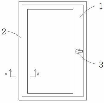
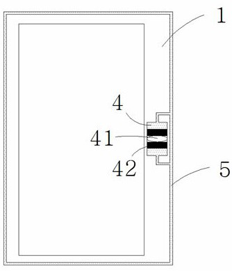
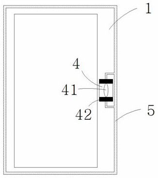
[0015] like Figure 1 to Figure 5 As shown, the windproof window includes a window frame 1 and a wall frame 2, the window frame 1 is provided with a handle 3, and the switch of the window lock is controlled by rotating the handle 3; the window frame 1 is provided with a cylindrical hollow Cavity 4, to accommodate the cam 41 coaxially connected with the handle 3, and a piston 42 that is restricted and close to the cam 41 is provided above and below the cam 41, and the cam 41 rotates with the handle 3 Drive the piston 42 to move up and down in the cavity 4; wherein when the handle 3 is in the unlocked state, the long axis of the cam 41 is horizontal, as figure 2 As shown; when the handle 3 is in the locked state, the major axis of the cam 41 is vertical, as image 3 shown, and push the piston 42 to the top and bottom of the cavity 4 respectively; the cavity 4 ext...
PUM
 Abstract
Description
Claims
Application Information