Wall mounting structure of assembled M-type lightgage steel joists

A light steel keel and installation structure technology, applied in building construction, covering/lining, construction, etc., can solve the problems of increasing construction costs, increasing working hours, affecting the installation of wall panels, etc., to ensure smoothness and improve installation. Quality and the effect of reducing construction costs

Pending Publication Date: 2020-01-07
GOLD MANTIS FINE DECORATION TECH SUZHOU CO LTD
View PDF0 Cites 2 Cited by
  • Summary
  • Abstract
  • Description
  • Claims
  • Application Information

AI Technical Summary

Problems solved by technology

Among them, the selected horizontal light steel keel has the following problems: 1. There are 38 and 50 light steel keels in the market, and the fastening screws protrude from the finished surface of the keel after being fixed, which affects the installation of wall panels; 2. Type 38 and 50 The 50-type light steel keel is installed as a single piece at a time, which increases the man-hour process. In addition, the installer needs to support the installation with his hands. When the span is large, two workers are required to cooperate and install together, which virtually increases the construction cost. ; 3. Type 38 and Type 50 light steel keels are single-product components, which cannot be effectively connected and installed with leveling parts. They need to be pressed and supported, and locked and fixed by fastening screws to form an overall wall keel system

Method used


Image

  • Wall mounting structure of assembled M-type lightgage steel joists
  • Wall mounting structure of assembled M-type lightgage steel joists
  • Wall mounting structure of assembled M-type lightgage steel joists

Examples


Embodiment 1

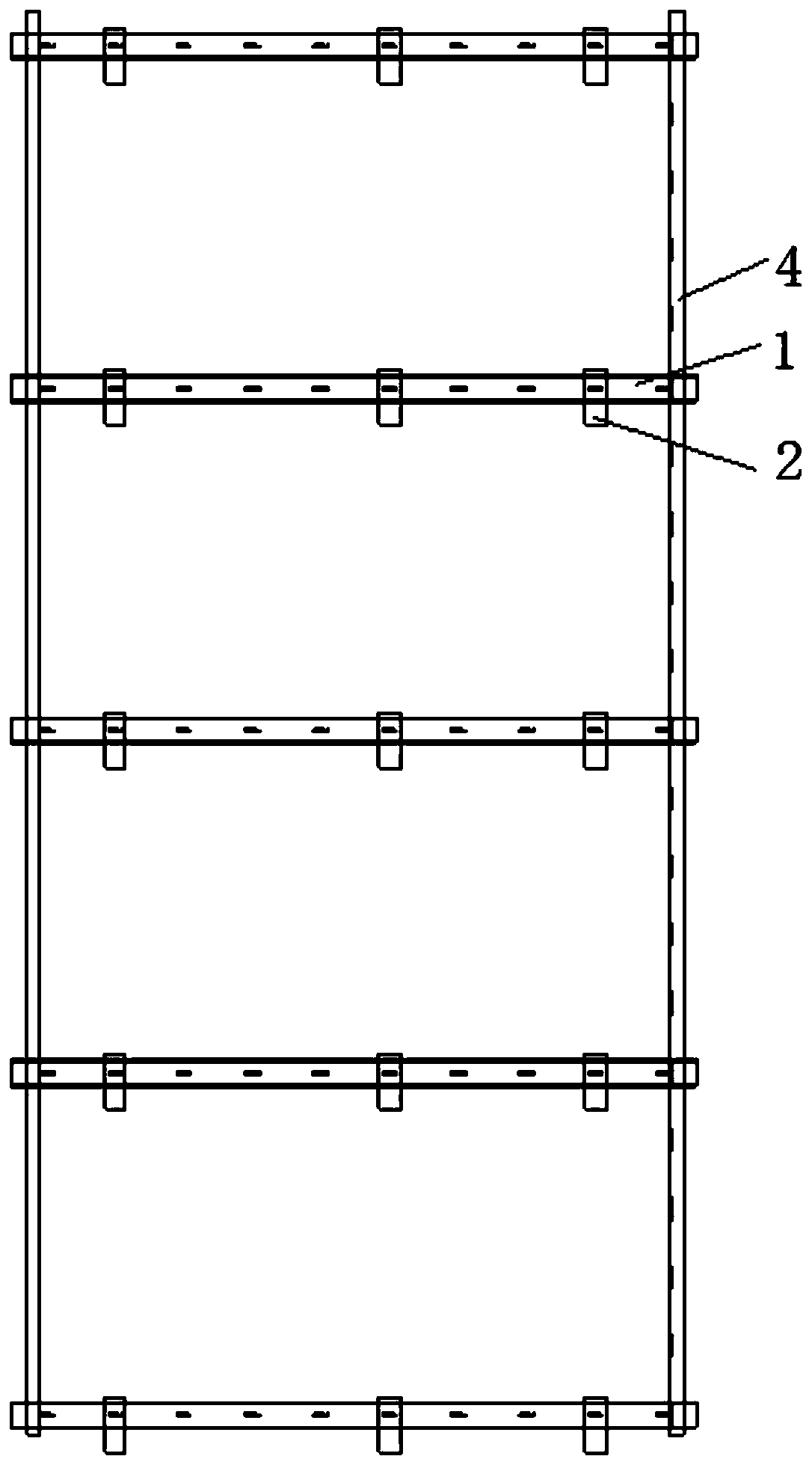
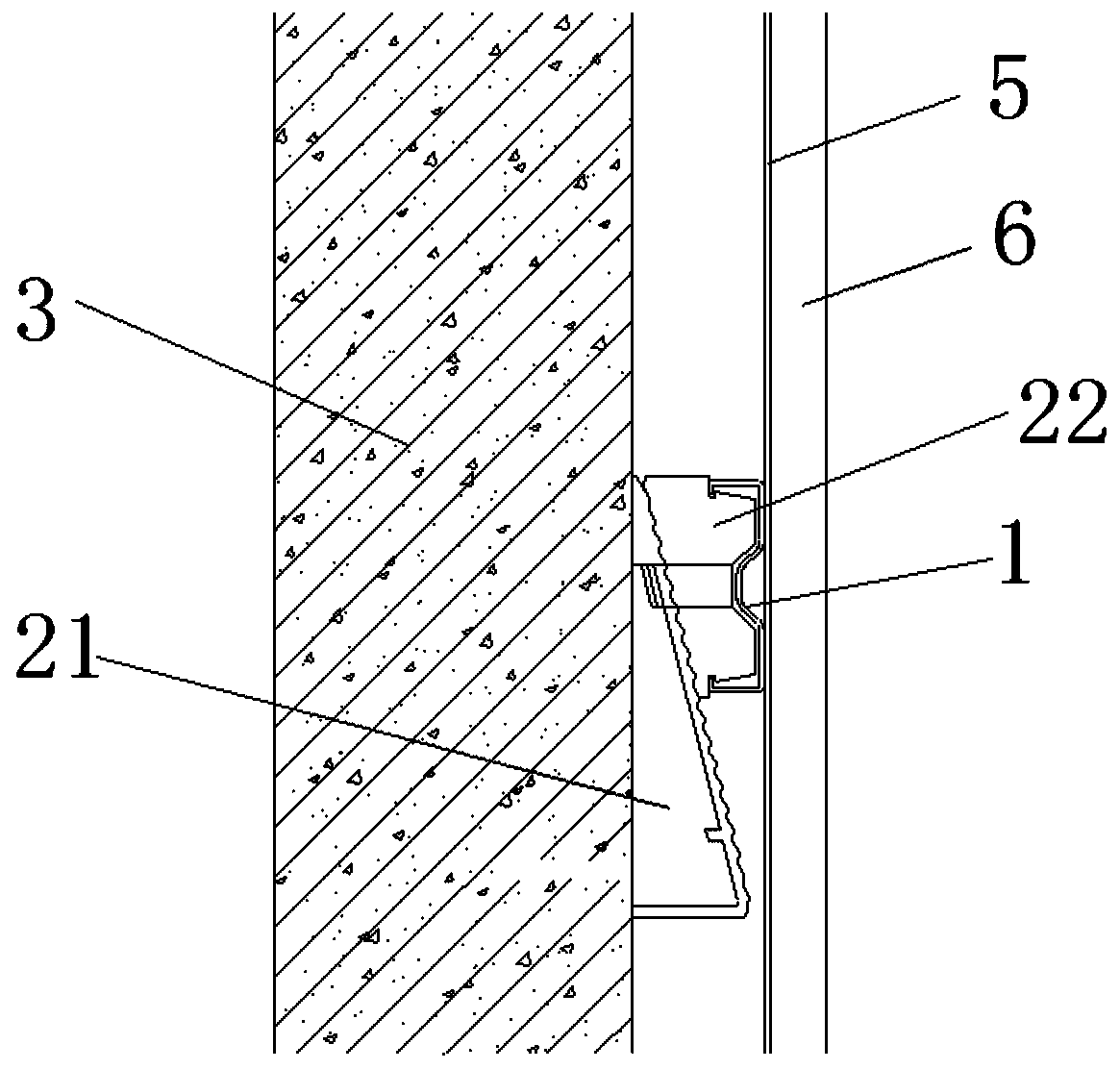
[0037] see Figure 1-2 , Figure 4-7 , the figure shows a wall installation structure of an assembled M-shaped light steel keel provided by Embodiment 1 of the present invention, which includes: M-shaped light steel keel 1, arranged along the horizontal direction, and two M-shaped light steel keels 1 The bottom of the side is provided with an inwardly bent clamping part 11; a leveling assembly 2, which includes a base 21 and a leveling seat 22 arranged on the base 21, the base 21 is fixed on the base wall 3, and the leveling seat 22 The inner clamping base 21, the outer side of which is clamped with the M-shaped light steel keel 1; the cassette 4 is arranged along the vertical direction, and both sides of the cassette 4 are uniformly and symmetrically provided with flanging buckles 41; the M-shaped light steel keel The middle position of 1 is connected with leveling assembly 2, and the leveling assembly 2 is evenly distributed along the length direction of the M-shaped light ...

Embodiment 2

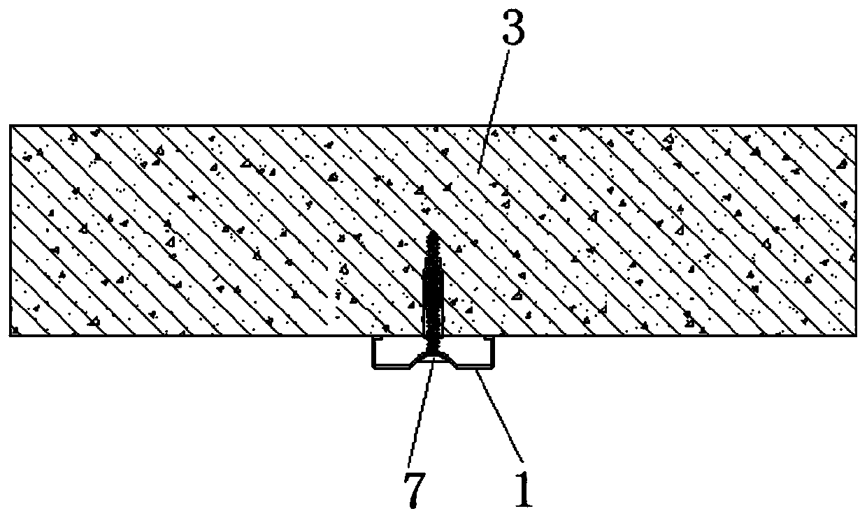
[0046] see Figure 3-4, the figure shows a wall installation structure of an assembled M-shaped light steel keel provided by Embodiment 2 of the present invention. On the basis of the above-mentioned embodiments, this embodiment further makes the following technologies as improvements Solution: In the middle of the top of the M-shaped light steel keel 1, an inwardly recessed connecting groove 12 is arranged, and the connecting groove 12 is arranged along the length direction of the M-shaped light steel keel 1; connecting holes 13 are evenly distributed in the connecting groove 12 , the distance between two adjacent connecting holes 13 is 100 mm. Through the setting of the above structure, the M-type light steel keel 1 can be fixedly connected with the base wall 3 through the screw 7, the screw 7 is located in the connection hole 13 in the connection groove 12, and the screw 7 will not protrude from the surface of the keel, so the screw 7 It is a subsidence connection, which c...

Embodiment 3

[0048] see figure 2 , Figure 7 , the figure shows a wall installation structure of an assembled M-shaped light steel keel provided by Embodiment 3 of the present invention. On the basis of the above-mentioned embodiments, this embodiment further makes the following technologies as improvements Solution: the side of the base 21 is triangular, and the inclined surface 211 is the connecting surface, and the adjusting seat 22 is clipped to the inclined surface 211; 221 is engaged with the clamping part 11; the side of the adjustment seat 22 is "M" shaped, and the card slot 221 is located on the upper and lower sides of the adjustment seat 22; along the inclined surface 211 of the base 21, the base 21 is provided with at least two connection Slot 212 ; a connecting rod 222 is arranged in the adjusting seat 22 , and the connecting rod 222 engages with the connecting groove 212 ; connecting teeth 23 are provided on the connection surfaces of the base 21 and the adjusting seat 22 ....


PUM


Abstract

The invention provides a wall mounting structure of assembled M-type lightgage steel joists. The wall mounting structure includes the M-type lightgage steel joists, leveling components, clamping belts, aluminum alloy vertical lines and wall panels; the bottoms of the two sides of each M-type lightgage steel joist are provided with clamping portions bent inwards; each leveling component includes abase and a leveling base arranged on the base, each base is fixed to a base layer wall, the inner side of each leveling base is clamped to the corresponding rbase, and the outer side of each levelingbase is clamped to the corresponding M-type lightgage steel joist; the two sides of each clamping belt are evenly and symmetrically provided with edge turning buckles; the leveling components are connected to the middle positions of the M-type light steel keels; the clamping belts are clamped on the two sides of each M-type lightgage steel joist, and the clamping portions and the edge turning buckles are clamped; the aluminum alloy vertical lines are fixedly connected to the M-type lightgage steel joists; and the wall panels are fixedly connected to the aluminum alloy vertical lines. Comparedwith the prior art, the wall mounting structure has the following advantages that different installation accessories can be installed in a matched manner to form an overall structural system, installation is facilitated, the installation efficiency is improved, and the construction cost is reduced; and meanwhile, the flatness of the decorative wall panels is improved.

Description

technical field [0001] The invention relates to a wall installation structure of a light steel keel, in particular to a wall installation structure of an assembled M-shaped light steel keel. Background technique [0002] Prefabricated decoration is a new form of decoration construction in recent years. As the name implies, prefabricated decoration is to complete the production of various parts and components required for decoration in the factory, and then transport them to the decoration site for assembly and installation, eliminating the need for traditional decoration on-site measurement and cutting of various parts and components. The construction is simpler and more convenient, which can greatly improve the construction efficiency of the decoration site, and the construction site is more tidy and beautiful, and will not produce too much decoration material waste. It is a more green and environmentally friendly form of decoration construction. [0003] At present, in th...

Claims


Application Information

Patent Timeline
Patent Type & Authority Applications(China)
IPC IPC(8): E04F13/23E04F13/25
CPCE04F13/0803E04F13/081
Inventor 陆晓朋于利凯何志伟
Owner GOLD MANTIS FINE DECORATION TECH SUZHOU CO LTD
Why Eureka
Try Eureka