Cutting table used for metal sectional material machining machine

A technology of metal profiles and processing machines, which is applied in the direction of metal processing machinery parts, metal processing equipment, manufacturing tools, etc., can solve the problems of inconvenient cutting and insufficient fixation, and achieve the advantages of convenient cutting, insufficient fixation and convenient movement Effect

Inactive Publication Date: 2020-01-17
广东博恒金属制品有限公司
View PDF0 Cites 4 Cited by
  • Summary
  • Abstract
  • Description
  • Claims
  • Application Information

AI Technical Summary

Problems solved by technology

[0003] The purpose of the present invention is to provide a cutting table for metal profile processing machines, which has the advantages of convenient cutting of workpieces and improved fixity, and solves the problems of inconvenient cutting and insufficient fixation of existing metal profiles during cutting

Method used


Image

  • Cutting table used for metal sectional material machining machine
  • Cutting table used for metal sectional material machining machine
  • Cutting table used for metal sectional material machining machine

Examples


Embodiment

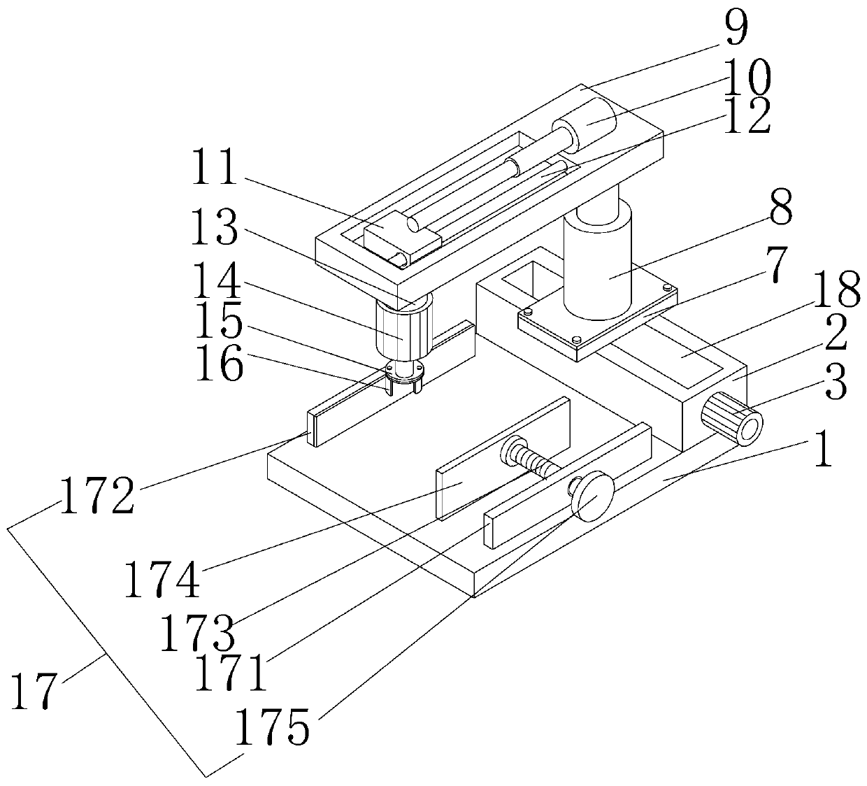
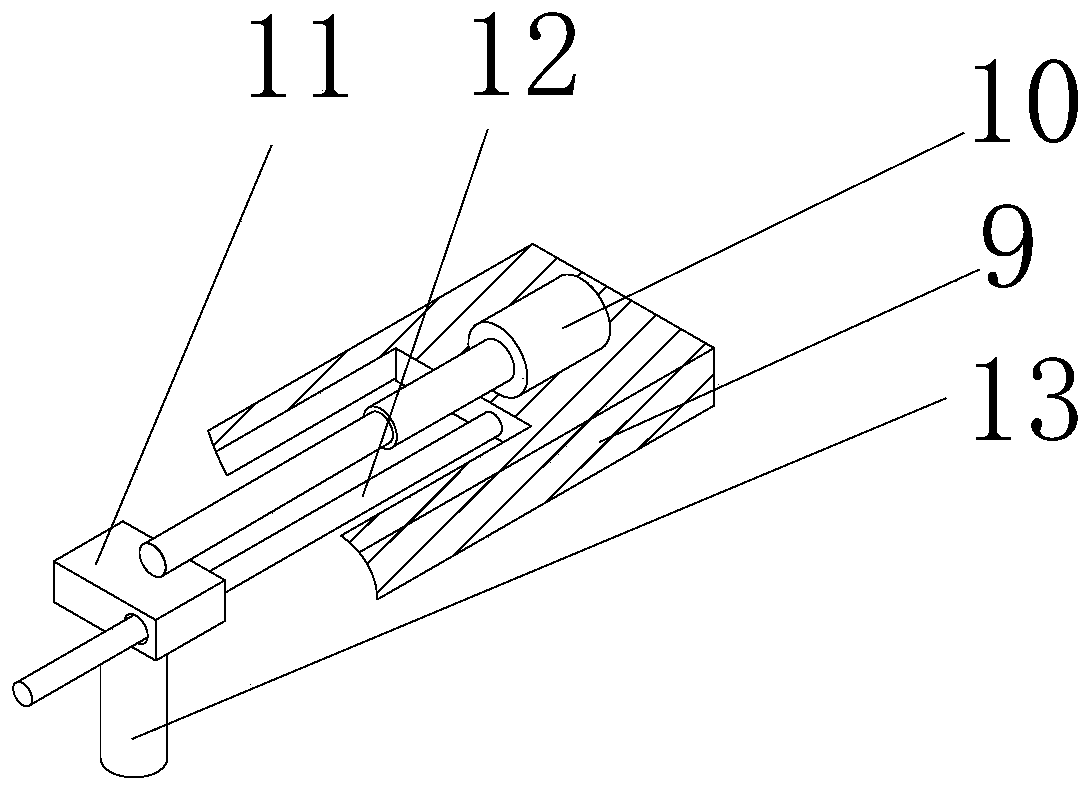
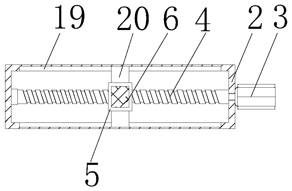
[0020] see Figure 1-3 , a cutting table for metal profile processing machines, including a support base 1, a box body 2 is fixedly connected to the right side of the top of the support base 1, a servo motor 3 is fixedly connected to the front of the box body 2, and the output shaft of the servo motor 3 runs through the box body 2 And extending to the inner cavity of the casing 2 is fixedly connected with a threaded rotating rod 4, the back of the threaded rotating rod 4 is rotatably connected with the inner wall of the casing 2 through a bearing, the surface of the threaded rotating rod 4 is threadedly connected with a threaded sleeve 5, and the threaded sleeve The top of the barrel 5 is fixedly connected with the moving plate 7 through the connecting plate 6, the top of the moving plate 7 is fixedly connected with the first electric cylinder 8 through screws, the top of the first electric cylinder 8 is fixedly connected with the support plate 9, and the top of the support pla...


PUM


Abstract

The invention discloses a cutting table for a metal sectional material machining machine. The cutting table comprises a supporting base. A box body is fixedly connected with the right side of the topof the supporting base. A servo motor is fixedly connected to the front face of the box body. An output shaft of the servo motor penetrates the box body and extends to an inner cavity of the box bodyto be fixedly connected with a threaded rotating rod. The back face of the threaded rotating rod is rotationally connected with the inner wall of the box body through a bearing. By means of the cutting table used for the metal sectional material machining machine, due to the cooperation of the servo motor, the threaded rotating rod, a threaded sleeve, a connecting plate and a moving plate, a firstelectric air cylinder is driven to move front and back, meanwhile, the first electric air cylinder drives the supporting plate to move vertically, a second electric air cylinder slides on a sliding rod through a sliding sleeve to drive a rotating motor to move left and right, meanwhile, the rotating motor drives a cutting tool to cut a metal workpiece, a clamping mechanism is used for clamping the metal workpiece, the cutting fixing performance is also improved while cutting is facilitated, and the cutting difficulty of machining personnel on the workpiece is lowered.

Description

technical field [0001] The invention relates to the technical field of metal profile cutting, in particular to a cutting table for a metal profile processing machine. Background technique [0002] The interaction between the cutting tool and the workpiece and their respective changing laws in the metal cutting process is a discipline. When designing machine tools and cutting tools, formulating cutting processes and quotas for machine parts, rationally using cutting tools and machine tools, and controlling the cutting process, It is necessary to use the research results of metal cutting principles to make the processing of machine parts economical, high-quality and high-efficiency. At present, most of the existing cutting methods are to first use clips to fix the profile, and then manually take the manual cutting machine Cutting the profiles is inconvenient and has the defect of insufficient fixity. Therefore, we propose a cutting table for metal profile processing machines. ...

Claims


Application Information

Patent Timeline
Patent Type & Authority Applications(China)
IPC IPC(8): B23D79/00B23Q1/25B23Q3/06B23Q5/34
CPCB23D79/00B23Q1/25B23Q3/06B23Q5/34
Inventor 孔庆麟
Owner 广东博恒金属制品有限公司
Why Eureka
Try Eureka