A road bridge crossing device used for water pipes in construction engineering

A technology of construction engineering and water pipes, which is applied in roads, buildings, roads, etc., can solve the problems of easy damage and service life of water pipes, and achieve the effects of improving service life, avoiding crushing, and alleviating rolling

Active Publication Date: 2021-11-30
安徽洪雷工业技术有限公司
View PDF9 Cites 0 Cited by
  • Summary
  • Abstract
  • Description
  • Claims
  • Application Information

AI Technical Summary

Problems solved by technology

[0003] The purpose of the present invention is to provide a road bridge crossing device for water pipes in construction projects. Through the bearing mechanism, support base, several buffer linkage mechanisms and joint devices, the water pipes can be protected to avoid the water pipes from being broken when vehicles pass through the water pipes. , to solve the problem of easy damage and low service life of water pipes

Method used


Image

  • A road bridge crossing device used for water pipes in construction engineering
  • A road bridge crossing device used for water pipes in construction engineering
  • A road bridge crossing device used for water pipes in construction engineering

Examples


Embodiment 1

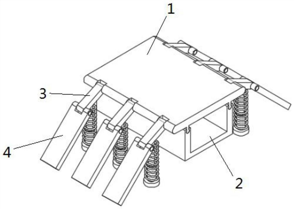
[0032] see Figure 1-6 As shown, a road bridge device for water pipes in construction projects includes a load-bearing mechanism 1, a support seat 2, several buffer linkage mechanisms 3 and connecting plates 4;

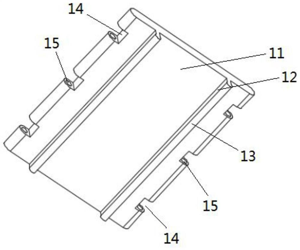
[0033] The carrying mechanism 1 includes a support platform 11, two mutually parallel raised bars 12 are fixed on the lower surface of the support platform 11, and the raised rails 13 are fixed on the raised bars 12, and a plurality of first rectangular grooves 14 are arranged on both sides of the support platform 11. , the distance between two adjacent first rectangular grooves 14 on the same side is the same, and the first hinge holes 15 are opened on both sides of the first rectangular groove 14;

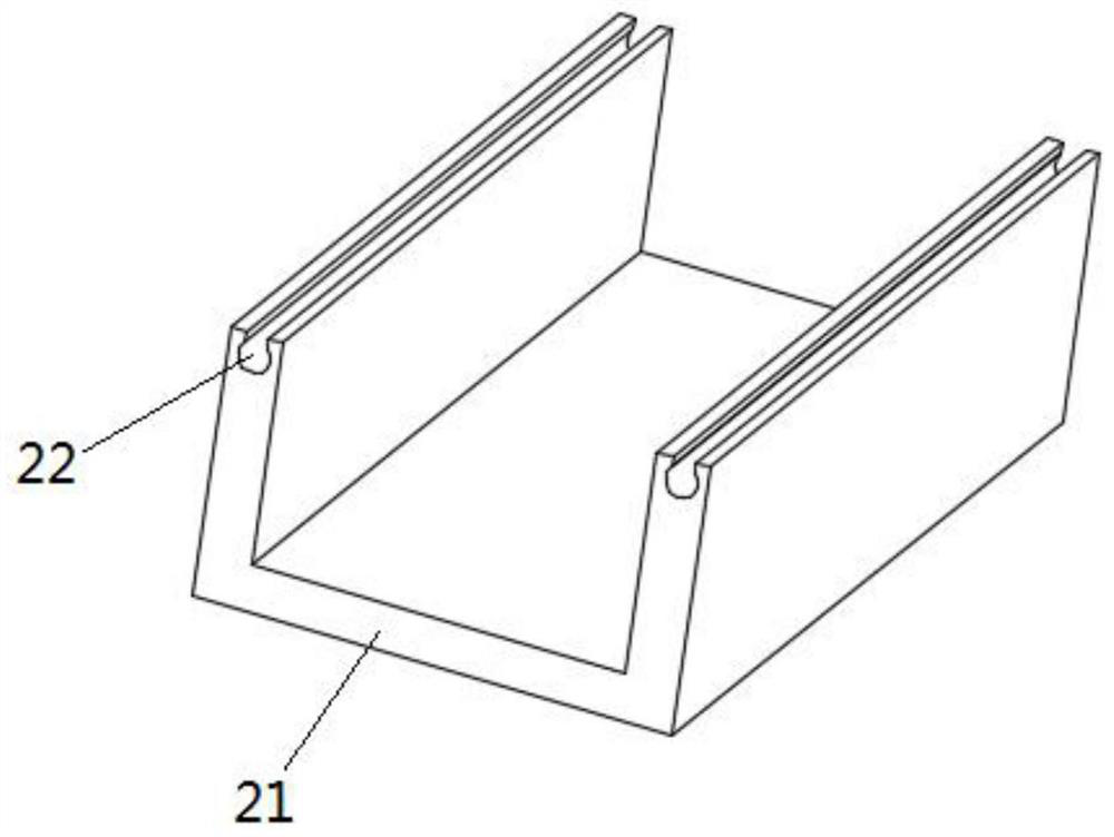
[0034] The support base 2 includes a U-shaped support frame 21, the upper surface of the two ends of the U-shaped support frame 21 is provided with a sliding groove 22 that is slidingly matched with the convex rail 13, the support base 2 moves along the length direction ...

Embodiment 2

[0041] On the basis of Embodiment 1, the shape of the connecting plate is changed, and the auxiliary anti-slip mechanism 6 is added, such as Figure 7-10 As shown, the engaging mechanism 5 includes an engaging plate, the engaging plate 51 is arc-shaped, and the radius of curvature of the arc is larger than the radius of curvature of the automobile tire, and one end of the engaging plate 51 has a third hinge hole 52, and the other end has a fourth hinge hole 53 .

[0042]Auxiliary anti-skid mechanism 6 comprises several anti-skid mechanisms 61 and connecting mechanism 62, and anti-skid mechanism 61 comprises anti-skid plate 611, and the two ends of anti-skid plate 611 two sides are respectively provided with socket hole 612, and connecting mechanism 62 comprises connecting plate 621, and connecting plate 621 two Insertion columns 622 are respectively fixed on the ends, and the insertion columns 622 cooperate with the insertion holes 612 to realize the connection of two adjacent...


PUM


Abstract

The invention discloses a road bridge crossing device used for water pipes in construction engineering, which includes a bearing mechanism, a support seat, several buffer linkage mechanisms and connecting devices; There are several first rectangular grooves, and first hinge holes are opened on both sides of the first rectangular groove; the buffer linkage mechanism includes a linkage plate, a limit column, a buffer base and a buffer spring; the buffer base includes a guide cylinder, and the guide cylinder is fixed to the bottom plate Connection, the guide cylinder is fixed with a bedding pillar, and the buffer spring is sleeved on the buffer base and the limit post; one end of the joint device is connected with the second hinge post on the linkage plate. The present invention effectively protects the water pipes from being crushed by vehicles, reduces the damage of vehicles to the road bridge device, effectively alleviates the vehicle's crush on the road bridge device, has the function of shock absorption, and improves the safety of the road bridge device. service life and stability of use.

Description

technical field [0001] The invention belongs to the technical field of construction engineering and relates to a road bridge crossing device used for construction engineering water pipes. Background technique [0002] At the construction site, water needs to be transported. The way to transport water is to use soft water pipes. The water pipes can be bent according to needs to meet the water supply requirements of different locations and different distances. Since the construction site is an open environment, the soft water pipes have been exposed to the sun for a long time , will gradually harden. If the vehicle passes through the hardened water pipe, it is very easy to cause the water pipe to break due to the rolling of the water pipe, especially the water pipe is broken due to the rolling of the vehicle or the rolling of the equipment, which wastes water resources. Once the water pipe The rupture will affect the materials and equipment of the construction site. In order t...

Claims


Application Information

Patent Timeline
Patent Type & Authority Patents(China)
IPC IPC(8): F16L7/00F16F15/04E01C11/24E01C9/08
CPCE01C9/08E01C11/24F16F15/04F16L7/00
Inventor 朱惜惜
Owner 安徽洪雷工业技术有限公司
Why Eureka
Try Eureka