Sand conveying and mixed discharging system and control method

A control method and mixing technology, applied in chemical instruments and methods, mixers, earth-moving drilling, etc., can solve the problem of unusable whole line, and achieve the advantages of simple and convenient control scheme, simplified equipment structure, and reduced equipment volume. Effect

Active Publication Date: 2020-04-14
中石化四机石油机械有限公司 +2
View PDF21 Cites 3 Cited by
  • Summary
  • Abstract
  • Description
  • Claims
  • Application Information

AI Technical Summary

Problems solved by technology

In the prior art, a single-line production system is mostly used, that is, one manifold is set up for one mixed row. When there is a problem with a manifold or a problem with a mixed row device, the entire line cannot be used.

Method used


Image

  • Sand conveying and mixed discharging system and control method
  • Sand conveying and mixed discharging system and control method
  • Sand conveying and mixed discharging system and control method

Examples


Embodiment 1

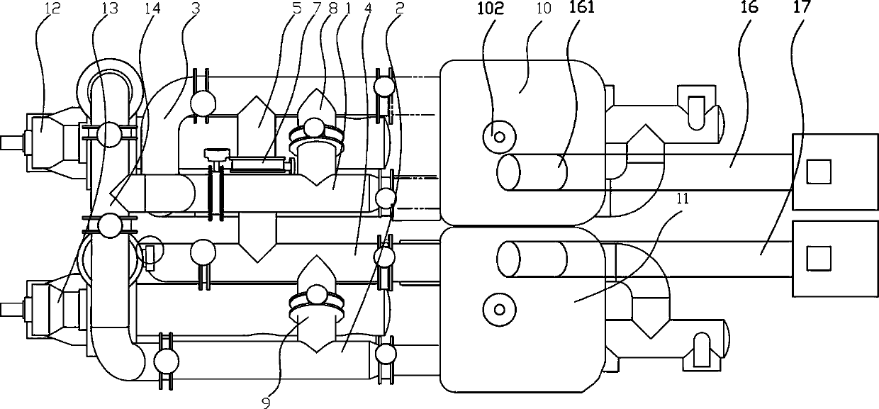
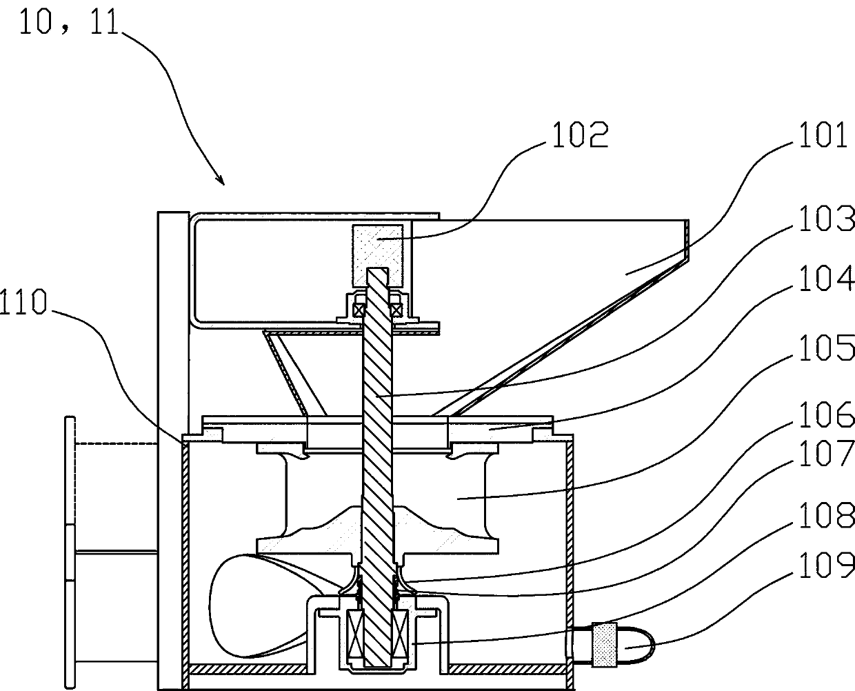
[0040] like figure 1 , 4 , 5, 6, 8, a kind of sand conveying mixed discharge system, it comprises mixing device, is provided with airtight tank body 110 in mixing device, the top of tank body 110 is provided with feed hopper 101, feed hopper 101 The booster impeller 105 driven to rotate by the drive device is provided below, the booster impeller 105 is provided with a top opening communicating with the feed hopper 101, and a side wall opening is also provided to feed the material by the centrifugal force of the booster impeller 105 rotation. The granular material in the bucket 101 is thrown into the tank body 110 from the side wall opening;

[0041] The mixed drainage inlet pipeline and the mixed drainage outlet pipeline are in communication with the tank body 110, a liquid supply pump is provided on the mixed drainage inlet pipeline, an output pressure sensor is arranged on the mixed drainage outlet pipeline, and an output pressure sensor is installed on the mixed drainage i...

Embodiment 2

[0071]like Figure 1~8 Among them, a control method using the above-mentioned sand conveying mixed discharge system includes the following steps:

[0072] S1. Based on the output pressure value of the output pressure sensor, compare the output pressure value with the preset output pressure value;

[0073] S2. When the output pressure value is higher than the preset output pressure value, reduce the speed of the driving device of the liquid supply pump to reduce the pressure of the liquid medium input into the tank 110 of the mixing device, and the speed of the driving device of the liquid supply pump Feedback adjustment according to the input pressure sensor to form a closed-loop control;

[0074] When the output pressure value is lower than the preset output pressure value, then increase the rotational speed of the driving device of the liquid supply pump to increase the pressure of the liquid medium input into the tank 110 of the mixing device, and the rotational speed of t...


PUM


Abstract

The invention provides a sand conveying and mixed discharging system and a control method. The sand conveying and mixed discharging system comprises a mixed discharging device, the structure of the mixed discharging device is characterized in that a feeding hopper is arranged at the top of a tank body, a main shaft is vertically arranged in the tank body by penetrating the feeding hopper, the mainshaft is connected with a driving device driving the main shaft to rotate, a booster impeller is arranged below the feeding hopper, the booster impeller is fixedly connected with the main shaft and rotates along with the main shaft, a top opening is formed in the middle of the top of the booster impeller, the bottom of the feeding hopper communicates with the top opening, a side wall opening is formed in the side wall of the booster impeller, the top opening communicates with the side wall opening, a bearing seat is arranged at the bottom of the main shaft, and a sealing device is arranged between the main shaft and the end part of the bearing seat. According to the system, through the arrangement of the structure of the booster impeller, the centrifugal force can be utilized to maintainthe pressure in the tank body, so that an additional pressurized feed tank is not arranged, the equipment structure is greatly simplified, the installation space of the equipment is reduced, and the equipment volume is reduced.

Description

technical field [0001] The invention relates to the field of fracturing equipment, in particular to a sand conveying and mixing discharge system and a control method. Background technique [0002] In the field of oil and natural gas production, the mixing device is the core equipment in the fracturing construction. The existing mixing device needs to mix the sand with the fracturing fluid solvent. The fracturing fluid solvent usually uses liquid carbon dioxide or liquid propane as the solvent . In the sand mixing tank of the mixing device, the pressure needs to be maintained. The existing construction plan is to add sand quantitatively to suppress the pressure. After the sand is used up, stop the operation and add sand and then suppress the pressure for construction. Continuous construction cannot be performed. Chinese patent document CN106761648A records a fracturing sand mixing device, a fracturing method, and a sand mixing equipment. In the prior art, a single-line prod...

Claims


Application Information

Patent Timeline
Patent Type & Authority Applications(China)
IPC IPC(8): E21B43/267B01F15/02B01F15/00
CPCE21B43/267B01F35/2113B01F35/71731
Inventor 尹进李龙杰吴汉川周益文黄勇李力张骥刘灼
Owner 中石化四机石油机械有限公司
Why Eureka
Try Eureka