
Large-span weak-rigidity gantry flexible hole forming device
A hole-making device and a large-span technology, applied in feeding devices, manufacturing tools, boring/drilling, etc., can solve the problems of high installation position of guide rails, poor stability, and reduced moving cost, so as to ensure local accuracy and stability The effects of high precision, precise control of hole making precision, and improvement of hole making precision
- Summary
- Abstract
- Description
- Claims
- Application Information
AI Technical Summary
Problems solved by technology
Method used
Image

Examples
Embodiment Construction
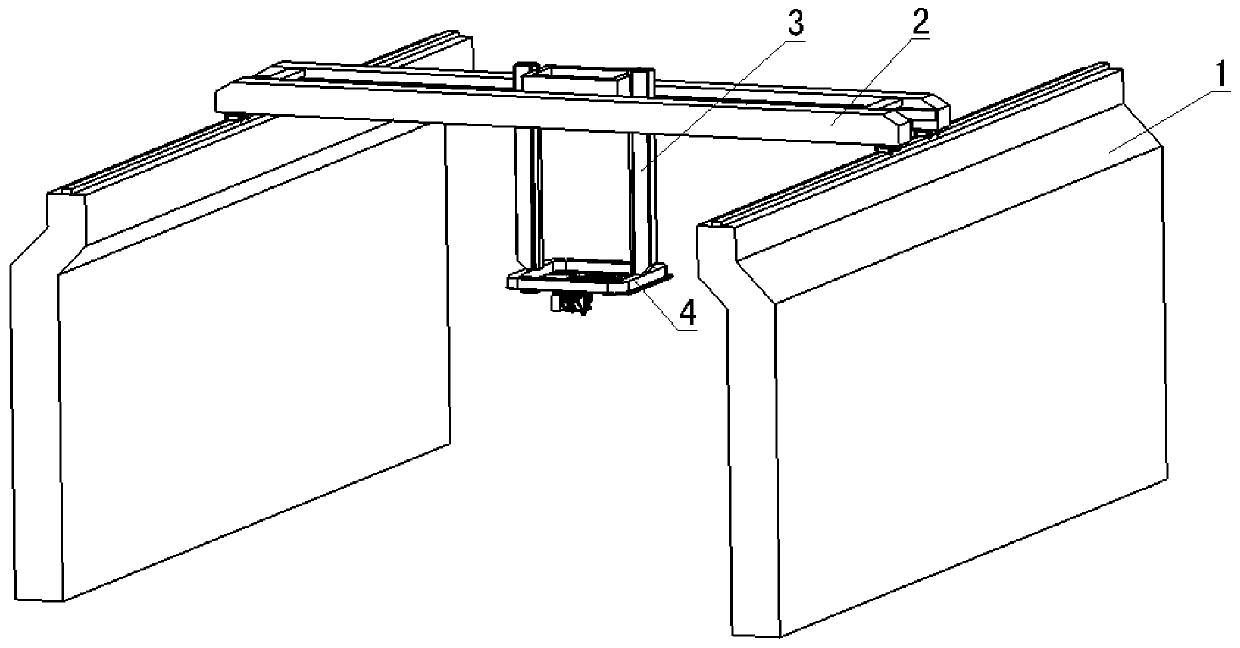
[0012] Referring to the accompanying drawings, the present invention is a device for realizing large-span gantry-type flexible drilling.
[0013] From figure 1 In the middle view, the supporting structure 1 and the sliding beam 2 are non-rigid bodies, which only provide a certain stability support for the mechanism. The two supporting structures 1 stand opposite each other, the sliding beam 2 spans the two supporting structures 1, and the lifting column 3 is fixed On both sides of the fixing seat 4, the fixing seat 4 is driven to move up and down in the vertical direction.
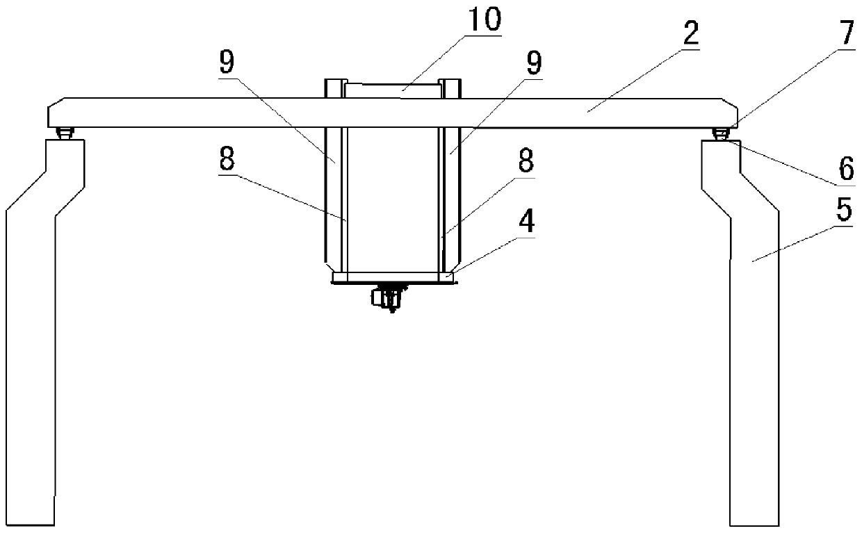
[0014] From figure 2 In the middle view, the two support structures 1 include a support body 5 and a square rail 6, the square rail 6 is installed on the top end surfaces of the two support bodies 5, the sliding beam 2 is a frame structure, spanning the two support bodies 5, and the bottom Both ends are provided with pulleys 7 that cooperate with the square rail 6, and can slide along the support body 5...
PUM
 Abstract
Description
Claims
Application Information