Ultra-wideband radar single-channel digital beam forming method based on space-time coding array

An ultra-wideband radar, space-time coding technology, applied in radio wave measurement systems, radio wave reflection/re-radiation, instruments, etc., can solve the problems of beam pattern shape distortion, decreased angular resolution, and high side lobe levels

Active Publication Date: 2020-05-01
XIDIAN UNIV
View PDF9 Cites 8 Cited by
  • Summary
  • Abstract
  • Description
  • Claims
  • Application Information

AI Technical Summary

Problems solved by technology

This method requires the sampling rate of the ADC to be slightly larger than the signal bandwidth, which is convenient for the application of ultra-wideband radar, but its defect is that the number of symbols introduced into the space code is limited by the number of array elements in the array, and the code elements of the space code The smaller the number, the higher the sidelobe level of the distance dimension and angle dimension of the DBF output signal
In addition, at the receiving end, the time-domain convolution matching filter method is used to obtain the output signal of the DBF. The DBF of the time-domain convolution requires that the sampling rate of the ADC must be an integer multiple of the sampling rate of the matched filter function. Usually, the sampling rate of the ADC is fixed. However, the sampling rate of the single-channel DBF matched filter function of UWB radar will change with the change of the beam pointing angle, so when the beam pointing angle is large, the shape of the beam pattern obtained by this method is distorted, That is, the main lobe of the beam pattern broadens, the zero point of the side lobe disappears, and the angular resolution decreases

Method used


Image

  • Ultra-wideband radar single-channel digital beam forming method based on space-time coding array
  • Ultra-wideband radar single-channel digital beam forming method based on space-time coding array
  • Ultra-wideband radar single-channel digital beam forming method based on space-time coding array

Examples


Embodiment Construction

[0053] The present invention will be further described below in conjunction with the accompanying drawings and specific embodiments.

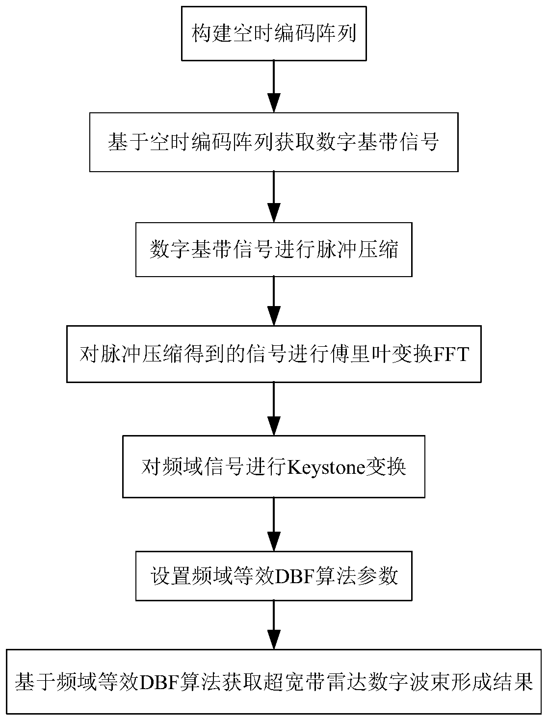
[0054] refer to figure 1 , the present invention comprises the following steps:

[0055] Step 1) Construct the space-time encoding array:

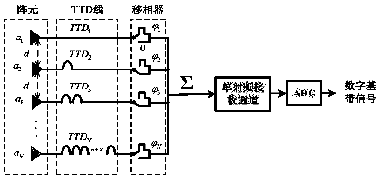
[0056] build as figure 2 The space-time coding array shown includes N array elements a which are arranged periodically and the arrangement period is d=λ / 2 1 ,a 2 ,...,a n ,...,a N , N real-time delay TTD lines TTD 1 ,TTD 2 ,...,TTD n ,...,TTD n , N phase shifters Sequentially connected single RF receive channels and sampling rate f s The analog-to-digital conversion device ADC, N array elements are connected in parallel with a single radio frequency receiving channel, and the nth real-time delay TTD line TTD n and the nth phase shifter Load the nth array element a sequentially n on the connection line with the single RF receiving channel, and put a 1 As a reference array element, N array e...


PUM


Abstract

The invention provides an ultra-wideband radar single-channel digital beam forming method based on a space-time coding array, and aims to reduce the sidelobe level of the distance dimension and the angle dimension of a DBF output signal and improve the precision and the angle resolution of a beam pointing angle. The method comprises the following implementation steps of constructing a space-time coding array; obtaining a digital baseband signal based on the space-time coding array; performing pulse compression on the digital baseband signal; performing Fourier transform on the signal obtainedby pulse compression; performing Keystone transform on the frequency domain signal; setting frequency domain equivalent DBF algorithm parameters; and obtaining an ultra-wideband radar digital beam forming result based on a frequency domain equivalent DBF algorithm. According to the ultra-wideband radar single-channel digital beam forming method provided by the invention, the space-time coding array is constructed, and spatial coding is carried out on the array spatial domain signal, so that the sidelobe level of the distance dimension and the angle dimension of the DBF output signal is effectively reduced, the ultra-wideband radar digital beam forming result is obtained based on frequency domain equivalence, and the precision and the angle resolution of the beam pointing angle are effectively improved.

Description

technical field [0001] The invention belongs to the technical field of radar signal processing, and relates to a method for forming an ultra-wideband radar single-channel digital beam, in particular to a method for forming an ultra-wideband radar single-channel digital beam based on a space-time coding array. Background technique [0002] Beamforming can be divided into analog beamforming and digital beamforming DBF. DBF uses the aperture of the array and uses digital processing methods to compensate for the propagation path difference caused by the difference in the spatial position of the array sensor for the incident signal in a certain direction. The phase difference realizes the in-phase superposition of array signals, so as to realize the maximum energy reception in this direction, which is equivalent to forming a "beam" in a certain direction, so that the radar system can work effectively in the harsh electromagnetic interference environment, and measure the performanc...

Claims


Application Information

Patent Timeline
Patent Type & Authority Applications(China)
IPC IPC(8): G01S7/41G01S7/02G01S13/00
CPCG01S7/418G01S7/023G01S13/006
Inventor 刘楠郭凯斯张林让
Owner XIDIAN UNIV
Why Eureka
Try Eureka