
Three-leg supporting asteroid surface anchoring device based on impact type ultrasonic drill
An anchoring device and ultrasonic technology are applied in the field of anchoring devices on the surface of asteroids supported by three legs, which can solve the problems of easy bounce, the inability of asteroid probes to stably fix the surface of asteroids, and the small gravity, and achieve small reaction force and stability. High, simple structure design effect
- Summary
- Abstract
- Description
- Claims
- Application Information
AI Technical Summary
Problems solved by technology
Method used
Image

Examples
specific Embodiment approach 1
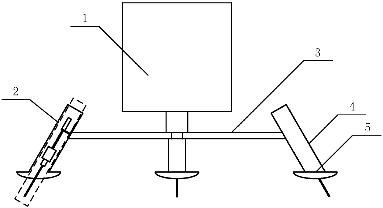
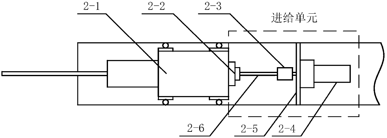
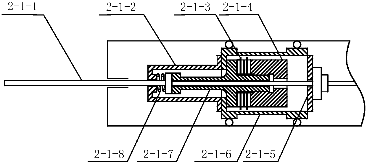
[0019] Specific implementation mode one, see Figure 1-Figure 3 Describe this embodiment, a three-leg support asteroid surface anchoring device based on an impact ultrasonic drill described in this embodiment includes three drilling anchor mechanisms 2, brackets 3, three support legs 4 and three support foot pads 5. The bracket 3 is installed at the bottom of the detector 1 and the three branches of the bracket 3 are evenly arranged at intervals of 120°, the supporting legs 4 are installed at the tail end of each branch of the bracket 3, and the supporting foot pads 5 are arranged on The bottom of the support leg 4 is used to improve the landing stability of the support leg 4, the inside of the support leg 4 is a hollow structure, the drilling anchor mechanism 2 is installed in the inside of the support leg 4 and one end passes through the support foot pad 5 ; The anchor drilling mechanism 2 includes an impact type ultrasonic drilling unit 2-1, a shaft coupling 2-3, a drive mo...
PUM
 Abstract
Description
Claims
Application Information