Circuit and method for achieving speed regulation of direct-current motor by utilizing voltage regulation

A DC motor, voltage regulation technology, applied in the direction of electronic commutation motor control, excitation or armature current control, electrical components, etc., can solve the problems of unstable performance of push rod speed regulation, high cost, increased circuit noise and radiation, etc. , to achieve the effect of simple structure, excellent reliability and precision, and low comprehensive cost

Pending Publication Date: 2020-06-02
CHANGZHOU KAIDI ELECTRICAL INC
View PDF0 Cites 0 Cited by
  • Summary
  • Abstract
  • Description
  • Claims
  • Application Information

AI Technical Summary

Problems solved by technology

[0008] The technical problem to be solved by the present invention is: at present, the H-bridge circuit and chopping adjustment are used to adjust multiple push rods synchronously, but these methods are costly, the noise and radiation in the circuit are greatly increased, and the speed regulation performance of the push rods is not good. Therefore, a method and circuit for realizing DC motor speed regulation by voltage regulation are proposed

Method used


Image

  • Circuit and method for achieving speed regulation of direct-current motor by utilizing voltage regulation
  • Circuit and method for achieving speed regulation of direct-current motor by utilizing voltage regulation
  • Circuit and method for achieving speed regulation of direct-current motor by utilizing voltage regulation

Examples


Embodiment Construction

[0028] The present invention will now be described in further detail with reference to the drawings and preferred embodiments. These drawings are all simplified schematic diagrams, which merely illustrate the basic structure of the present invention in a schematic manner, so they only show the structures related to the present invention.

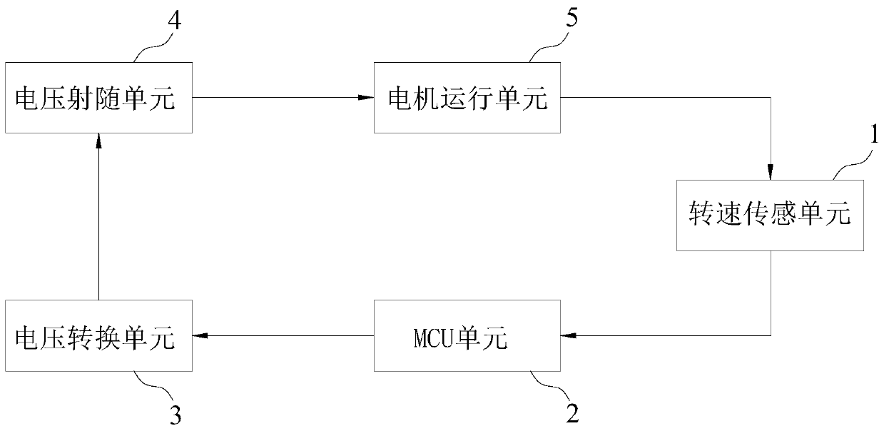
[0029] Reference figure 1 , Is the principle block diagram of the circuit for realizing DC motor speed regulation by voltage regulation according to the present invention. The circuit of the present invention includes a rotational speed sensing unit 1, an MCU unit 2 (such as a single-chip microcomputer), a voltage conversion unit 3, and a voltage follower unit 4, which are connected in sequence. The speed sensor unit 1, the voltage follower unit 4 are all connected to the motor operating unit 5. , The power supply unit provides power to the entire circuit. Compared with the voltage chopping speed regulation method generally used in the market ...


PUM


Abstract

The invention discloses a circuit for achieving speed regulation of a direct-current motor by utilizing voltage regulation. The circuit comprises a rotating speed sensing unit, an MCU unit, a voltageconversion unit and a voltage emitter following unit which are connected in sequence, wherein the rotating speed sensing unit is used for collecting a rotating speed signal of the motor; the MCU unitis used for receiving and analyzing the rotating speed signal and further outputting a PWM signal; the voltage conversion unit is used for converting the PWM signal into a voltage signal; and the voltage emitter following unit is used for regulating the voltage of the voltage signal and outputting the voltage signal to a motor operation unit. The invention further discloses a method for achievingspeed regulation of the direct-current motor by utilizing voltage regulation. The circuit has the advantages of simple structure, low comprehensive cost and more accurate detection; and the circuit isnot influenced by radiation and electromagnetic interference, has better reliability and precision, and is particularly suitable for being applied when the direct-current motor adopts technologies such as back electromotive force and impedance to measure the rotating speed of the motor and needs to adjust the rotating speed of the motor.

Description

Technical field [0001] The invention relates to the technical field of electric furniture, furniture or electric decoration, in particular to a circuit and a speed regulation method for adjusting the speed of a DC motor by using an output voltage. Background technique [0002] With the continuous progress of science and technology and the improvement of people’s living standards, people are paying more and more attention to the comfort and functionality of furniture products based on the basic functions of furniture products. In order to meet the above requirements, DC drives The application of motors in this field is becoming more and more widespread and common. [0003] In the field of electric smart homes and furniture, in order to increase customer experience and product functionality, furniture manufacturers have begun to install push rod motors driven by micro-motors on furniture such as sofas, beds, desks, etc. Adjust the height, angle and other functions. For products tha...

Claims


Application Information

Patent Timeline
Patent Type & Authority Applications(China)
IPC IPC(8): H02P7/29H02P6/182
CPCH02P7/29
Inventor 吴则信孙宜江孙瑶
Owner CHANGZHOU KAIDI ELECTRICAL INC
Why Eureka
Try Eureka