Electromechanically drivable brake pressure generator for hydraulic braking system of vehicle and vehicle including electromechanical brake pressure generator

A braking pressure and hydraulic braking technology, which is applied in road vehicle drive control systems, brakes, brake transmissions, etc., can solve the problems of large structures, achieve effective manufacturing, compact design, and reduce energy loss.

Pending Publication Date: 2020-10-30
ROBERT BOSCH GMBH
View PDF9 Cites 0 Cited by
  • Summary
  • Abstract
  • Description
  • Claims
  • Application Information

AI Technical Summary

Problems solved by technology

However, when the reduction ratio is relatively low, the multistage spur gear transmission produces a considerable distance in the radial direction relative to the spindle transmission unit, so that the entire structural group of this electromechanical brake pressure generator is constructed. quite large

Method used


Image

  • Electromechanically drivable brake pressure generator for hydraulic braking system of vehicle and vehicle including electromechanical brake pressure generator

Examples


Embodiment Construction

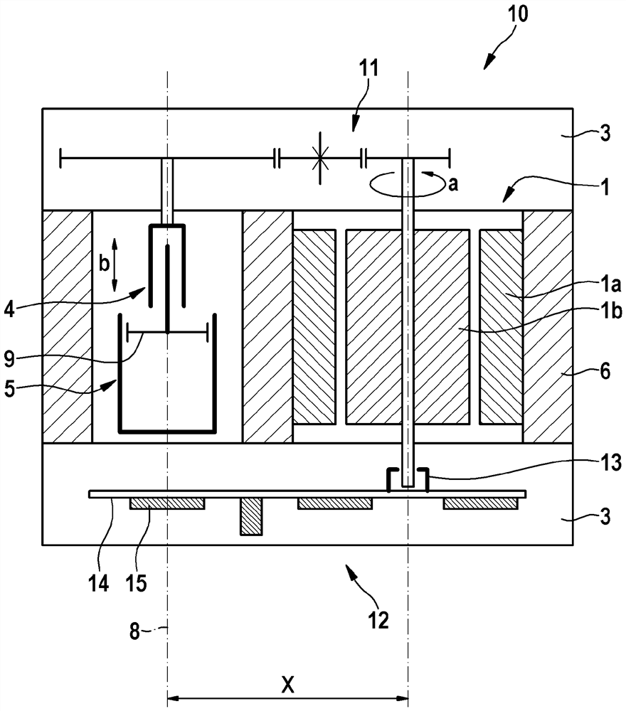
[0018] according to figure 1 , the electric motor unit 1 generates a driving rotational movement a in accordance with a predetermined braking requirement. The electric motor unit 1 essentially consists of a stator 1 a arranged stationary relative to the hydraulic block 6 and a rotor 1 b corresponding thereto, which is connected to a shaft 7 . The electric motor unit 1 is actuated via an electronic control unit 2 . The rotational movement a thus produced is converted by the reduction gear unit 3 with the spindle drive unit 4 on the output side into a translational movement b for the piston actuation of the hydraulic piston / cylinder unit 5 .

[0019] In the compactly constructed electromechanical brake pressure generator, the hydraulic block 6 made of light metal for the piston / cylinder unit 5 also accommodates the electric motor unit 1 in the sense of functional integration, thus making it possible to dispense with its separate housing. In this case, the motor shaft 7 of the...


PUM


Abstract

The invention relates to an electromechanically drivable brake pressure generator for a hydraulic braking system of a vehicle, including an electric motor unit (1), which is activatable with the aid of an electronic control unit (2) in accordance with a brake pressure to be applied and whose rotary motion (a) generated thereby is converted by a reducing gearbox unit (3) including an output-side spindle drive unit (4) into a translatory motion (b) for actuating a piston of a hydraulic piston / cylinder unit. A hydraulic block (6) of the piston / cylinder unit (5) also at least partially accommodates the electric motor unit (1) in such a way that a motor shaft (7) of the electric motor unit (1) extending at least predominantly in the area of the hydraulic block (6) is situated axially parallel to a longitudinal axis (8) of the piston (9) of the piston / cylinder unit (5) which is movable in the hydraulic block.

Description

technical field [0001] The invention relates to an electromechanically actuatable brake pressure generator for a hydraulic brake system of a vehicle according to the features of the preamble of claim 1 and to an electromechanically actuatable brake pressure generator according to the features of claim 10 . Generator vehicle. The electromechanical brake pressure generator is equipped with an electric motor unit which can be actuated by an electronic control unit according to the brake pressure to be applied, a reduction gear unit with a spindle drive unit on the output side will The resulting rotational movement of the electric motor unit is converted into a translational movement for actuating the piston of the hydraulic piston / cylinder unit. [0002] Future drive concepts for motor vehicles require alternative brake-force buildup devices, since the low pressure is no longer available for driving conventional vacuum brake boosters. The electromechanical brake pressure genera...

Claims


Application Information

Patent Timeline
Patent Type & Authority Applications(China)
IPC IPC(8): B60T17/02B60T13/66B60T13/12
CPCB60T17/02B60T13/66B60T13/12B60T13/745B60T13/746B60T13/662B60T13/686F16H55/06F16H1/02H02K5/20H02K11/215H02K7/003B60Y2400/81B60Y2400/60B60Y2300/60B60Y2306/05F15B2211/526F15B2015/206F15B15/088
Inventor M.伯姆C.奥厄勒M.格赖纳
Owner ROBERT BOSCH GMBH
Why Eureka
Try Eureka