Low-voltage transformer area topology rapid identification system

A low-voltage station area and identification system technology, applied in information technology support systems, sustainable buildings, instruments, etc., can solve problems such as unreliability, complex electrical wiring, and low-voltage station area topology errors, and achieve reliable identification and implementation. Promote and trigger efficient effects

Active Publication Date: 2020-11-13
JIANGSU INTELEVER ENERGY TECH CO LTD
View PDF7 Cites 1 Cited by
  • Summary
  • Abstract
  • Description
  • Claims
  • Application Information

AI Technical Summary

Problems solved by technology

However, due to the large number of distribution stations of the power company and the complexity of electrical wiring, there is still a phenomenon of private construction and random construction. Especially in some old residential areas and remote areas, due to various load adjustments that have not been filed and adjusted in time and listing errors, etc., the power supply department Obtaining the original topological relationship information during the construction of the station area is usually incomplete and unreliable
[0003] There are three main reasons for the wrong topological relationship of the low-voltage station area: (1) errors in the files of the electric meter of the user during the construction of the low-voltage station area, resulting in an error in the topology of the low-voltage station area; (2) insufficient attention to the station area, and only recording The information of some station areas caused the loss of topological information of some low-voltage station areas; (3) when the low-voltage station area failed, there was no record or wrong record when the wiring was adjusted during the inspection and emergency repair, resulting in the topological error of the low-voltage station area

Method used


Image

  • Low-voltage transformer area topology rapid identification system
  • Low-voltage transformer area topology rapid identification system
  • Low-voltage transformer area topology rapid identification system

Examples


Embodiment Construction

[0035] The present invention is described in further detail now in conjunction with accompanying drawing. These drawings are all simplified schematic diagrams, which only illustrate the basic structure of the present invention in a schematic manner, so they only show the configurations related to the present invention.

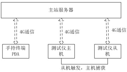
[0036] Such as figure 1 As shown, the low-voltage platform topology rapid identification system of the present invention includes a PDA handheld terminal, a master station server and a low-voltage platform topology rapid identification instrument, and the low-voltage platform topology rapid identification instrument includes an identification instrument host and an identification instrument slave, and the identification instrument host , the slave machine of the recognition instrument and the PDA handheld terminal are respectively connected to the server of the master station through the 4G communication module.

[0037] The PDA handheld terminal sends the "S...


PUM


Abstract

The invention relates to a low-voltage transformer area topology rapid identification system and belongs to the technical field of intelligent power grids and intelligent power utilization. The systemcomprises a PDA hand-held terminal, a main station server and a low-voltage transformer area topology rapid identification instrument, wherein the low-voltage transformer area topology rapid identification instrument comprises an identification instrument host and an identification instrument slave, the identification instrument host, the identification instrument slave and the PDA hand-held terminal are connected with the master station server through the 4G communication module, the identification instrument slave machine comprises a slave machine trigger circuit, the slave trigger circuitcomprises an MCU pulse control circuit, a triode switch circuit and a solid-state relay JD1, a trigger signal output end of the MCU pulse control circuit is connected with the weak current end of thesolid-state relay JD1 through the triode switch circuit, and a strong current end of the solid-state relay JD1 is connected with the AC 220V phase voltage of a to-be-tested transformer area through the load resistor R1. The system can solve a problem that the topological relation of the low-voltage transformer area is not clear, and meets the requirements of electric power companies and power supply departments for quickly identifying the topological structure of the low-voltage transformer area.

Description

technical field [0001] The invention relates to a fast topology identification system for a low-voltage station area, which belongs to the technical fields of smart grid and smart electricity utilization. Background technique [0002] In many old communities and remote areas in China, there are problems such as confusion in the filing of power projects and unclear topology of the station area. At present, due to the lack of accurate line topology diagrams in many low-voltage station areas, it is difficult to quickly and accurately troubleshoot problems when a line fails, and there are problems of low troubleshooting efficiency, long cycle time, and high cost. A lot of manpower, material resources, and financial resources were wasted, and the final problem could not be effectively solved. To solve this problem, the common practice under the current technology is to rely on the power supply department to provide the topology data of the station area saved during the construct...

Claims


Application Information

Patent Timeline
Patent Type & Authority Applications(China)
IPC IPC(8): G01R31/00H02J13/00H02J3/00
CPCG01R31/00H02J3/00H02J13/00001H02J13/00002H02J13/00022H02J13/00032Y02B90/20Y02E60/00Y04S40/126
Inventor 王永生张自变耿树军邓士伟苗青
Owner JIANGSU INTELEVER ENERGY TECH CO LTD
Why Eureka
Try Eureka