Refrigerant flow-dividing equipment for air conditioner, and using method thereof

A technology for shunting equipment and refrigerants, applied in refrigerators, refrigeration components, mechanical equipment, etc., can solve problems affecting the normal operation of air conditioners, uneven mixing of gas-liquid two-phase refrigerants, etc., to weaken the influence of gravity on refrigerants , improve mixing uniformity, and ensure the effect of normal shunting

Active Publication Date: 2020-12-18
佛山市艺兴冷气工程有限公司
View PDF17 Cites 5 Cited by
  • Summary
  • Abstract
  • Description
  • Claims
  • Application Information

AI Technical Summary

Problems solved by technology

[0004] The purpose of the present invention is to solve the problem that the uneven mixing of gas-liquid two-phase refrigerants in the existing design affects the normal operation of the air conditioner, and proposes a refrigerant splitting device for air conditioners and its use method

Method used


Image

  • Refrigerant flow-dividing equipment for air conditioner, and using method thereof
  • Refrigerant flow-dividing equipment for air conditioner, and using method thereof
  • Refrigerant flow-dividing equipment for air conditioner, and using method thereof

Examples


Embodiment 1

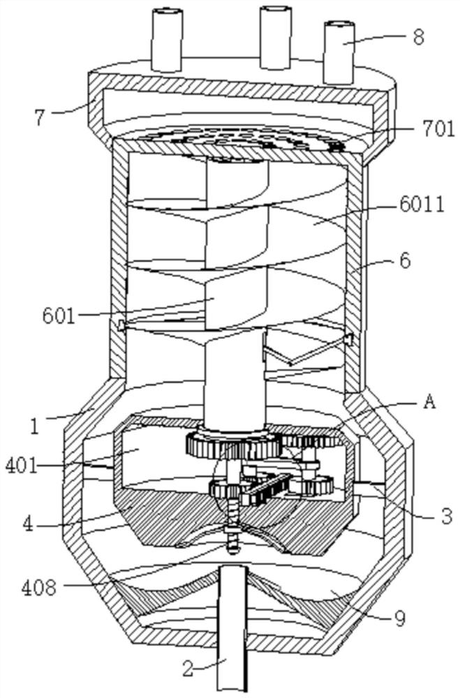
[0039] refer to Figure 1-5 , a kind of air-conditioning refrigerant distribution equipment, comprising a housing 1, the bottom of the housing 1 is provided with a liquid inlet, the inner wall of the liquid inlet is connected with a liquid inlet pipe 2, and the inner walls of both sides of the housing 1 are connected with a connecting plate 3, A shunt block 4 is connected between the two connecting plates 3, and the bottom wall of the shunt block 4 is dug with an arc-shaped groove 5, and the arc-shaped groove 5 is placed above the liquid inlet pipe 2, and the top of the housing 1 is connected with a conveying Cavity 6, the housing 1 and the delivery cavity 6 communicate with each other, the inner wall of the delivery cavity 6 is rotatably connected with a rotating tube 601, the outer wall of the rotating tube 601 is fixed with a spiral delivery blade 6011, and a cavity 401 is dug in the shunt block 4, and the cavity The inner wall of 401 is dug with a groove 4011, the inner wa...

Embodiment 2

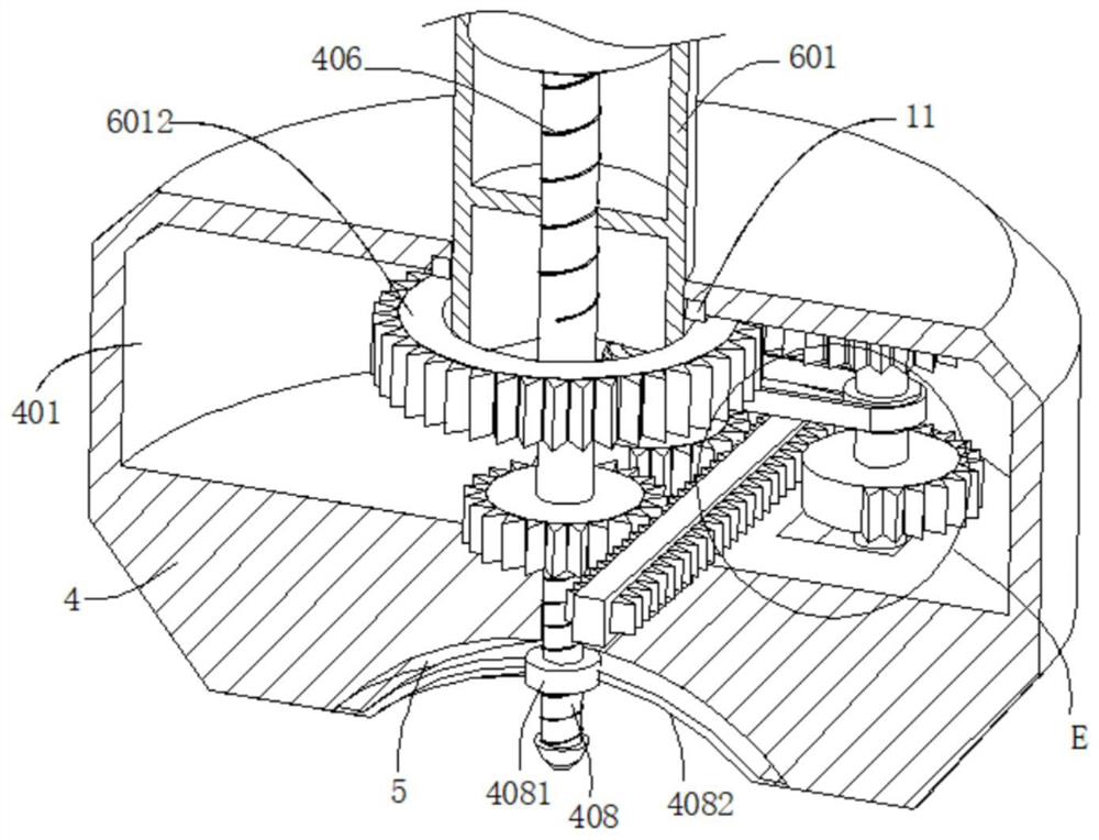
[0042] refer to figure 1 , figure 2 , image 3 , Figure 4 , Figure 5 , Figure 6 , Figure 8 and Figure 9 , an air-conditioning refrigerant splitting device, which is basically the same as Embodiment 1, furthermore, the outer wall of the rotating shaft 4013 is connected with a first gear 4015, the inner wall of the cavity 401 is rotatably connected with a rotating rod 402, and the outer wall of the rotating rod 402 is connected with a The second gear 4021, the first gear 4015 and the second gear 4021 are all set as half gears, and the outer wall of the rotating rod 402 and the rotating shaft 4013 is connected with a matching synchronous wheel 403, and a synchronous belt 4031 is connected between the two synchronous wheels 403.

[0043] The inner wall of the cavity 401 is slidably connected with a moving plate 404 , and the outer walls of both sides of the moving plate 404 are connected with first racks 4041 , and the two first racks 4041 mesh with the first gear 4015...

Embodiment 3

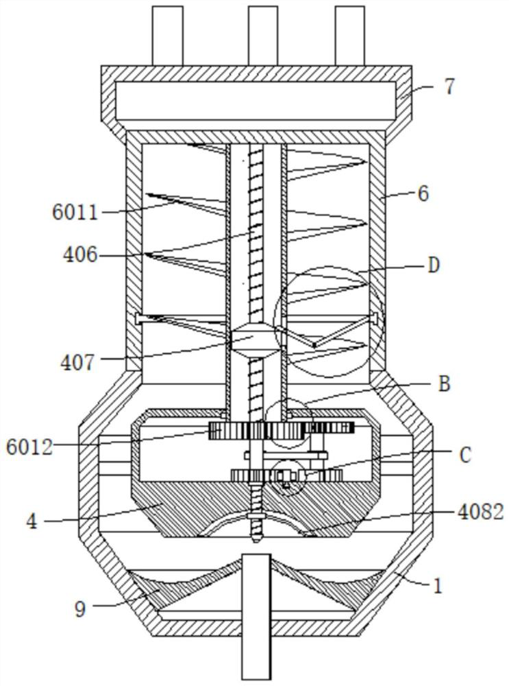
[0049] refer to Figure 1-10 , an air-conditioning refrigerant splitting device, which is basically the same as that of Embodiment 1, furthermore, the outer wall of the third gear 4061 away from the first screw 406 is connected with a second screw 408, and the second screw 408 passes through the arc The groove 5 extends outwards, the outer wall of the second screw rod 408 is threadedly connected with a moving sleeve 4081, the outer wall of the moving sleeve 4081 is connected with an elastic net 4082, and the end of the elastic net 4082 away from the moving sleeve 4081 is connected to the inner wall of the arc groove 5; The moving sleeve 4081 pulls the elastic net 4082 to vibrate up and down in the arc-shaped groove 5, and then the elastic net 4082 cuts the air bubbles, so that the gaseous refrigerant and the liquid refrigerant are evenly mixed.

[0050] The inner walls of both sides of the cavity 401 are dug with sealing chambers 10, the inner walls of the sealing chambers 10 ...


PUM


Abstract

The invention discloses refrigerant flow-dividing equipment for an air conditioner, and a using method thereof, and belongs to the technical field of air conditioner refrigeration. The refrigerant flow-dividing equipment for the air conditioner comprises a shell body, wherein a liquid inlet port is formed in the bottom of the shell body; a liquid inlet pipe is connected to the inner wall of the liquid inlet port; connecting plates are connected to the inner walls of the two sides of the shell body separately; a flow-dividing stop block is connected between the two connecting plates; an arc-shaped groove is dug in the bottom wall of the flow-dividing stop block, and formed above the liquid inlet pipe; a conveying cavity is connected to the top of the shell body; the shell body communicateswith the conveying cavity; a rotating pipe is rotationally connected to the inner wall of the conveying cavity; a spiral conveying blade is fixedly arranged on the outer wall of the rotating pipe; anempty cavity is dug in the flow-dividing stop block; a groove is dug in the inner wall of the empty cavity; and a driving motor is connected to the inner wall of the groove. According to the invention, the mixing uniformity of a gas-phase and liquid-phase mixed refrigerant is improved, normal flow-dividing for the refrigerant is ensured, and then the problem that the normal work of the air conditioner is influenced due to non-uniform mixing for the gas-phase and liquid-phase refrigerant is effectively avoided.

Description

technical field [0001] The invention relates to the technical field of air-conditioning and refrigeration, in particular to an air-conditioning refrigerant distribution device and a method for using the same. Background technique [0002] In the refrigeration technology of air conditioners, heat exchange is realized through multi-flow heat exchangers. The multi-flow heat exchanger includes multiple flow paths. Generally, the gas-liquid two-phase refrigerant is passed into the refrigerant splitting device, and then the refrigeration The refrigerant splitting device supplies the gas-liquid two-phase refrigerant into multiple flow paths. When the gas-liquid two-phase refrigerant passes into the refrigerant splitting device, due to the effect of gravity, the gas-liquid two-phase refrigerant will be stratified. As a result, the gas-liquid two-phase refrigerant cannot enter each flow path evenly, resulting in too much liquid refrigerant in some flow paths, resulting in incomplete ...

Claims


Application Information

Patent Timeline
Patent Type & Authority Applications(China)
IPC IPC(8): F25B41/00F16J15/16F16H19/04B01D19/02B01F3/04
CPCF25B41/42
Inventor 唐正杰王伦
Owner 佛山市艺兴冷气工程有限公司
Why Eureka
Try Eureka