An array antenna for automotive radar sensor

An array antenna and automotive radar technology, which is suitable for antennas on movable objects, antenna arrays that are powered separately, antennas, etc., can solve problems such as difficult control of antenna radiation characteristics, failure to meet index requirements, and poor angular resolution. , to achieve the effect of miniaturization cost, low cost and high precision

Pending Publication Date: 2020-12-18
成都多普勒科技有限公司 +1
View PDF0 Cites 2 Cited by
  • Summary
  • Abstract
  • Description
  • Claims
  • Application Information

AI Technical Summary

Problems solved by technology

[0003] At present, the existing automotive millimeter-wave radar structure on the market mainly adopts the traditional microstrip line series-fed structure or series-fed array structure, the radiation characteristics of the antenna are difficult to control, and the processing consistency is poor; the suppressio

Method used


Image

  • An array antenna for automotive radar sensor
  • An array antenna for automotive radar sensor
  • An array antenna for automotive radar sensor

Examples


Embodiment Construction

[0021] The following will clearly and completely describe the technical solutions in the embodiments of the present invention with reference to the accompanying drawings in the embodiments of the present invention. Obviously, the described embodiments are only part of the embodiments of the present invention, not all of them. Based on the embodiments of the present invention, all other embodiments obtained by those skilled in the art without any creative effort fall within the protection scope of the present invention.

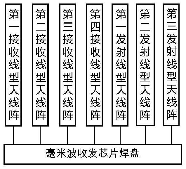
[0022] An array antenna for an automotive radar sensor provided in this embodiment includes millimeter wave transceiver chip pads, a first receiving linear antenna array, a second receiving linear antenna array, a third receiving linear antenna array, a fourth receiving linear antenna array, The receiving linear antenna array, the first transmitting linear antenna array, the second transmitting linear antenna array, and the third transmitting linear antenna arr...


PUM


Abstract

The invention discloses an array antenna for an automobile radar sensor, and the array antenna comprises a millimeter wave receiving and transmitting chip bonding pad, a first receiving linear antennaarray, a second receiving linear antenna array, a third receiving linear antenna array, a fourth receiving linear antenna array, a first transmitting linear antenna array, a second transmitting linear antenna array, and a third transmitting linear antenna array. The core architecture of the array antenna adopts a three-transmitting four-receiving antenna array mode, and adopts ten in-phase non-equal amplitude angle feed array elements as a basic unit structure to control the size and position of an antenna parasitic unit, reasonably suppress the sidelobe level of the antenna and optimize theradiation characteristics of the antenna. The impedance matching characteristic is improved by combining a combination method of tangential circular polarization and surface slotting of a symmetricalstructure . According to the scheme, high precision, high response speed and high resolution can be achieved, and a millimeter wave radar system scheme for medium-distance and long-distance detectioncan be achieved.

Description

technical field [0001] The invention relates to the technical field of vehicle-mounted millimeter-wave radar antennas, in particular to an array antenna for vehicle radar sensors. Background technique [0002] In recent years, automotive millimeter-wave radar technology has been developing rapidly as an advanced driver assistance system technology necessary for breakthrough future driverless technology. Compared with optical cameras and laser radars, vehicle-mounted millimeter-wave radars have all-weather detection capabilities that are not afraid of rain, fog, dust and haze, and have a long detection distance. At the same time, they have the advantages of high resolution and small size. Vehicle-mounted radars are divided into three main types according to distance: long-range, medium-range and short-range. Long-range radars usually use high-gain antennas to achieve long-distance detection requirements, but their field of view (FOV) is also rapidly decreasing, so they usual...

Claims


Application Information

Patent Timeline
IPC IPC(8): H01Q21/06H01Q1/32
CPCH01Q1/3233H01Q21/06
Inventor 邬海峰刘林盛江润坤陈金禄刘明辉张琳
Owner 成都多普勒科技有限公司
Why Eureka
Try Eureka