Automatic loading rod assembling device for SHPB test

A technology for automatic assembly and loading of rods, which is applied to measuring devices, instruments, scientific instruments, etc., and can solve problems such as long-term operation of unfavorable equipment and shortened cylinder life

Active Publication Date: 2021-01-08
BEIJING INSTITUTE OF TECHNOLOGYGY
View PDF13 Cites 0 Cited by
  • Summary
  • Abstract
  • Description
  • Claims
  • Application Information

AI Technical Summary

Problems solved by technology

However, in the process of dynamic loading, the propagation speed of the stress wave is much greater than the movement speed of the cylinder piston, and the stress wave generated by the collision between the impact rod and the incident rod will directly act on the cylinder piston. Under the environment of large load and high strain rate, the life of the cylinder will be greatly shortened, which is not conducive to the long-term operation of the equipment

Method used


Image

  • Automatic loading rod assembling device for SHPB test
  • Automatic loading rod assembling device for SHPB test
  • Automatic loading rod assembling device for SHPB test

Examples


Embodiment 1

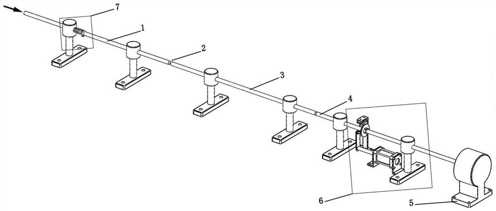
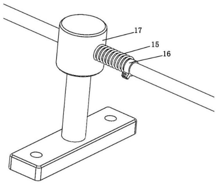
[0046] The diameter of the loading rod described in this embodiment is 16 mm, the lengths of the incident rod 1, the transmission rod 3 and the absorption rod 4 are all 1000 mm, and the loading rod is fixed on the operating platform with a T-shaped installation groove through the loading rod bracket 17 Above, the axis of the loading rod is 150mm away from the console. Use the SC50-100 type air cylinder, install it directly below the absorption rod through the pneumatic push rod bracket 9, the stroke of the pneumatic push rod 8 is 100mm, the diameter is 16mm, and the front end is provided with threads.

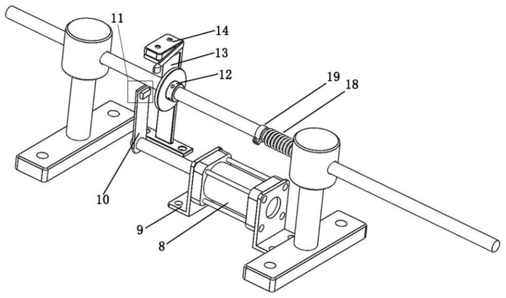
[0047] The traction piece 10 is a Q235 steel sheet of 3mm×25mm×100mm, one end has a Φ16mm through hole, and is fixed on the front end of the pneumatic push rod 8 through a nut, and the other end is provided with an M4 threaded hole. The NdFeB permanent magnets 23 with through holes are connected.

[0048] The traction flange 12 is a Q235 steel ring with an outer diameter of 40...

Embodiment 2

[0058] In this embodiment, a rod system with a diameter of 16 mm is used. The lengths of the incident rod 1, the transmission rod 3 and the absorption rod 4 are all 1000 mm. The loading rod is fixed on the console with a T-shaped mounting groove through the loading rod bracket 17. 150mm from the operating platform. Pneumatic push rod 8 uses SC50-100 type air cylinder, and is installed directly below the absorption rod through pneumatic push rod bracket 9. Pneumatic push rod 8 has a stroke of 100mm, a diameter of 16mm, and a thread at the front end.

[0059] The traction piece 10 is a Q235 steel sheet of 3mm×25mm×100mm, one end has a Φ16mm through hole, and is fixed on the front end of the pneumatic push rod through a nut; the other end of the traction piece 10 is provided with a Φ3mm through hole, and the M3 inner hexagon magnetic adjustment bolt passes The through hole is connected with the permanent magnet 23 in the magnetic force size adjusting member 11; the attraction for...


PUM

PropertyMeasurementUnit
diameteraaaaaaaaaa

Abstract

The invention relates to an automatic loading rod assembling device for an SHPB test, and belongs to the technical field of impact dynamics experiments. The device comprises a pneumatic push rod, a traction sheet, a traction flange, a magnetic force adjusting piece, a position sensor and a test sample pre-tightening assembly, the pneumatic push rod is fixed on the operation table, is positioned below an absorption rod and moves back and forth in the direction parallel to the axis of the absorption rod; the traction flange is sleeved and fixed on the absorption rod and has magnetic conductivity, one end of the traction sheet is connected with the pneumatic push rod, the other end of the traction sheet is provided with a magnetic force adjusting piece, the position sensor is fixed on the operation table and connected with a controller, and the position sensor is located above the position of the traction flange when a test sample is clamped; and the test sample pre-tightening assembly provides a pre-tightening force for the test sample. The device can be used for automatically assembling a loading rod in the SHPB test process, and is stable in performance and simple in structure.

Description

technical field [0001] The invention relates to an automatic assembly device for loading rods used for SHPB testing, belonging to the technical field of impact dynamics experiments. Background technique [0002] The split Hopkinson pressure bar system (SHPB) is one of the main devices for testing the dynamic mechanical properties of materials, which can realize the 2 the s -1 ~10 4 the s -1 Acquisition of mechanical property parameters under strain rate conditions. The traditional split Hopkinson bar is manually loaded and aligned with the loading bar (including the impact bar, incident bar, transmission bar and absorption bar) during the test, which is inefficient; It is easy to cause the contact between the test sample and the loading bar to be not tight, which will affect the experimental results. When performing dynamic compression experiments under high or low temperature conditions, manual assembly can easily lead to drastic changes in the temperature of the sampl...

Claims


Application Information

Patent Timeline
Patent Type & Authority Applications(China)
IPC IPC(8): G01N3/04G01N3/307
CPCG01N3/04G01N3/307G01N2203/001G01N2203/0019G01N2203/0044G01N2203/0222G01N2203/0411
Inventor 程焕武安瑞王扬卫周哲王琳
Owner BEIJING INSTITUTE OF TECHNOLOGYGY
Why Eureka
Try Eureka