Multi-station slicing machine

A slicer and multi-station technology, applied in the direction of manufacturing tools, work accessories, stone processing equipment, etc., can solve the problem of limiting the cutting capacity and efficiency of the slicer, requiring high technical level of installers, and unable to expand the production scale of the workshop area, etc. problems, to achieve the effect of facilitating centralized arrangement, avoiding interface breakage, and improving the utilization rate of plant space

Pending Publication Date: 2021-02-12
QINGDAO GAOCE TECH CO LTD
View PDF0 Cites 0 Cited by
  • Summary
  • Abstract
  • Description
  • Claims
  • Application Information

AI Technical Summary

Problems solved by technology

In the actual production process, the slicer often has only one cutting area assembly, that is, one cutting area, and one cutting area can only form one cutting station, which results in a cutting cycle that can only be used for hard and brittle materials on a single cutting station. Cutting severely limits the cutting capacity and efficiency of the slicer; increasing the number of slicers to improve the cutting capacity and efficiency will also bring about the problem of occupying more plant land. Many companies cannot achieve this because they cannot expand the plant area. Expand the production scale; increasing the number of slicers also means increasing the investment in equipment capital. For high-priced slicers, it is also a factor that makes it difficult for enterprises to expand the production scale; the realization of the heat exchange function of slicers requires many pipelines Circulating flow, while the existing equipment pipelines are relatively scattered, which is not conducive to management; the existing slicers usually require professional and technical personnel to carry out on-site installation work of up to several weeks, which is not conducive to serving long-distance customers, and the technical level of the installers Higher requirements and therefore higher personnel costs

Method used


Image

  • Multi-station slicing machine
  • Multi-station slicing machine
  • Multi-station slicing machine

Examples


Embodiment Construction

[0040] In order to make those skilled in the art better understand the technical solution of the present invention, the technical solution of the present invention is clearly and completely described below in conjunction with the accompanying drawings of the present invention. Based on the embodiments in this application, those of ordinary skill in the art will Other similar embodiments obtained without creative work shall all fall within the scope of protection of this application. In addition, the directional words mentioned in the following embodiments, such as "upper", "lower", "left", "right", etc., are only referring to the directions of the drawings, therefore, the directional words used are for illustration rather than limitation invent.

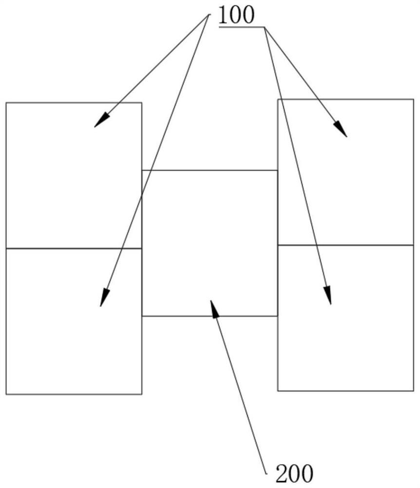
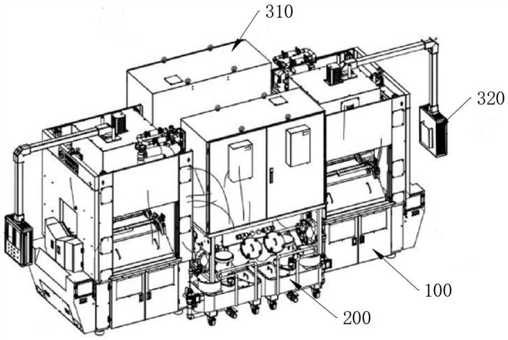
[0041] Such as Figure 1-14 As shown, a multi-station slicer includes at least two cutting area assemblies 100 for slicing, and a liquid circuit assembly 200 for providing cutting fluid and cooling liquid. The plurality of cutting a...


PUM


Abstract

The invention discloses a multi-station slicing machine. The multi-station slicing machine comprises at least two cutting area assemblies used for slicing and a liquid path assembly used for providingcutting liquid and cooling liquid, and the multiple cutting area assemblies share the liquid path assembly. The multi-station slicing machine has the following beneficial effects that by arranging the multiple cutting area assemblies, namely a plurality of cutting areas, the cutting capacity of the slicing machine can be improved by more than one time, the capacity is improved, the capacity per unit area is doubled, and the utilization rate of plant space can be improved; and meanwhile, the liquid path assembly and an oil gas assembly are arranged to be matched with the cutting area assemblies to complete cutting, and efficient and high-quality hard and brittle material cutting can be achieved.

Description

technical field [0001] The invention belongs to the field of silicon rod slicing, in particular to a multi-station slicing machine. Background technique [0002] Silicon wafer forming refers to the process of making silicon rods into silicon wafers. At present, the multi-wire cutting method is the most common method for slicing. In the actual production process, the slicer often has only one cutting area assembly, that is, one cutting area, and one cutting area can only form one cutting station, which results in a cutting cycle that can only be used for hard and brittle materials on a single cutting station. Cutting severely limits the cutting capacity and efficiency of the slicer; increasing the number of slicers to improve the cutting capacity and efficiency will also bring about the problem of occupying more plant land. Many companies cannot achieve this because they cannot expand the plant area. Expand the production scale; increasing the number of slicers also means in...

Claims


Application Information

Patent Timeline
Patent Type & Authority Applications(China)
IPC IPC(8): B28D5/04B28D7/02B28D7/00
CPCB28D5/0058B28D5/0064B28D5/0076B28D5/045
Inventor 张璐孙承政宫云庆范国强刘钢尚丰彦张新恺
Owner QINGDAO GAOCE TECH CO LTD
Why Eureka
Try Eureka