CT detector data transmission structure and CT detector data transmission method based on source synchronization LVDS-SERDES

A data transmission method and data transmission technology, applied in the field of CT detector data transmission structure based on source synchronous LVDS-SERDES, can solve the problem of high cost, and achieve the effects of strong applicability, cost reduction, and wide range of chip selection

Pending Publication Date: 2021-04-30
FMI MEDICAL SYST CO LTD
View PDF1 Cites 0 Cited by
  • Summary
  • Abstract
  • Description
  • Claims
  • Application Information

AI Technical Summary

Problems solved by technology

[0007] The purpose of the present invention is to overcome the problem of the high cost of using FPGA chips due to the use of Transceiver for data transmission in the existing CT detector internal data transmission structure, and the low-end FPGA chips are not equipped with Transceiver. Provides a source-synchronous LVDS-SERDES-based CT detector data transmission structure and data transmission method capable of saving costs, having a unified architecture and strong scalability

Method used


Image

  • CT detector data transmission structure and CT detector data transmission method based on source synchronization LVDS-SERDES

Examples


Embodiment 1

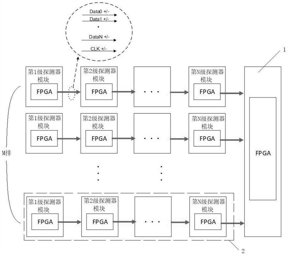
[0026] Such as figure 1 The shown CT detector data transmission structure based on source synchronous LVDS-SERDES includes data aggregation module 1 and M rows of detector groups 2, M≥2; each row of detector groups is connected to the data aggregation module; each row of detection Each detector group includes N detector modules, N≥2; in each row of detector groups, each detector module is serially connected; each detector module is equipped with an FPGA chip. Wherein, the value of M is usually 16 rows of detector groups, 64 rows of detector groups and 256 rows of detector groups. The invention can universally match the data transmission structure of detector groups with 16 rows, 64 rows, 256 rows or more.

[0027] Further, the detector groups in each row communicate with each other in parallel. The rows of detector groups in the structure of the present invention are in parallel, and the detector modules in each row of detector groups are in series. The present invention co...


PUM


Abstract

The invention belongs to the technical field of CT, and particularly relates to a CT detector data transmission structure and method based on source synchronization LVDS-SERDES. The CT detector data transmission structure comprises a data aggregation module and M rows of detector groups, wherein M is greater than or equal to 2; each row of detector groups is in communication connection with the data aggregation module; each row of detector groups comprises N detector modules, wherein N is greater than or equal to 2; in each row of detector groups, the detector modules are connected in series; and each detector module carries an FPGA chip. An FPGA chip is carried on the data aggregation module. The invention provides a novel series-parallel combined data transmission mode. According to the invention, the universal differential pins of the FPGA chip are used, so that the design is not limited by the number of Transeiver any more, and logic resources in the FPGA chip can be efficiently utilized. The method can save the cost, and has the characteristics of unified architecture and high expandability.

Description

technical field [0001] The invention belongs to the field of CT technology, and in particular relates to a source synchronous LVDS-SERDES-based CT detector data transmission structure and a data transmission method. Background technique [0002] In existing detectors, large quantities of data are transmitted between substrate clusters through the Transceiver, a dedicated hardware resource built into the FPGA. Since the wide-body detector is composed of dozens or even hundreds of modules, and each module is equipped with an FPGA chip, the work to be done by the FPGA chip is very simple, that is, to collect data from multiple ADs, and aggregate these data for backward level sending. In theory, you only need to use a very cheap FPGA chip with low logic density, but in reality, because the existing solutions use a dedicated high-speed serial transceiver Transceiver for data transmission, and the existing low-end FPGA chips are not Equipped with Transceiver. [0003] In additi...

Claims


Application Information

Patent Timeline
Patent Type & Authority Applications(China)
IPC IPC(8): G06F15/17G06F15/78
CPCG06F15/17G06F15/7807
Inventor 陈修儒黄振强倪健朱炯方泽利
Owner FMI MEDICAL SYST CO LTD
Why Eureka
Try Eureka