
A high-suction floating oil collection device

A collection device and high suction lift technology, which is applied in the direction of grease/oily substance/floating matter removal device, water treatment parameter control, separation method, etc., can solve the problems of high equipment maintenance rate, cost, unsatisfactory installation and maintenance separation effect, floating Low efficiency of oil collection and other problems, to achieve the effect of wide selection range, easy automatic operation, and automatic operation

Active Publication Date: 2022-03-18
黄海峰
View PDF10 Cites 0 Cited by
  • Summary
  • Abstract
  • Description
  • Claims
  • Application Information

AI Technical Summary

Problems solved by technology

[0003] The collection of oil slicks by adsorption has many disadvantages: the adsorption materials are consumables or vulnerable parts, and the consumable cost is high; the efficiency of oil slick collection is low, which may cause secondary pollution; the maintenance rate of equipment is high, etc.
Therefore, many people install suction equipment close to the water surface under such working conditions, and use positive pressure separation to collect oil slicks in order to reduce the requirements for suction lift. Some people also use adsorption methods to collect oil slicks, but Users are dissatisfied with these methods in terms of cost, installation and maintenance, separation effect, etc.

Method used


Image

  • A high-suction floating oil collection device
  • A high-suction floating oil collection device

Examples


Embodiment example 1

[0027] The utility model relates to a device for collecting floating oil with high suction lift.

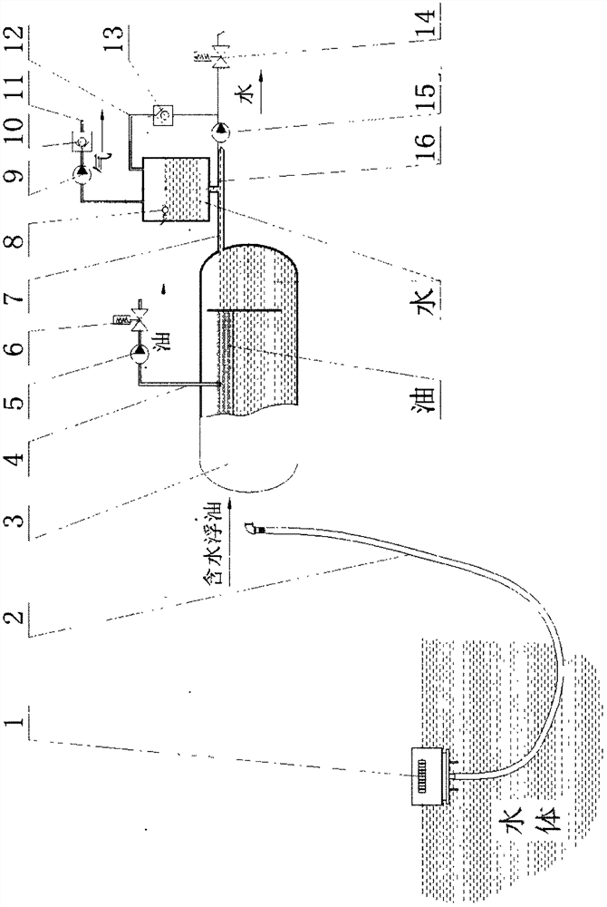
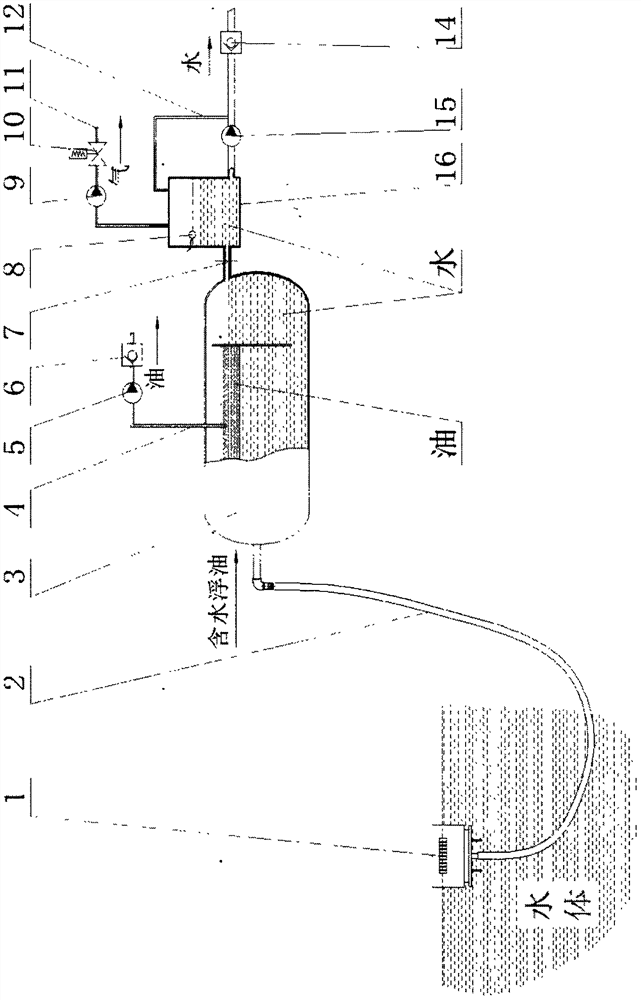
[0028] The oil collector 1 placed on the water surface communicates with the inlet port of the airtight oil-water separation device 3 through the oil suction hose 2, and the oil-water separation device 3 is a horizontal airtight negative pressure type oil separation tank; Normally closed oil discharge pipeline 4 and normally closed drain pipeline 7; described normally closed oil discharge pipeline 4 is equipped with oil pump 5 and valve 6, valve 6 is a one-way valve in this case; described normally closed drain pipeline 7 is equipped with a water pump 15 and a valve 14, and the valve 14 is a one-way valve in this case; an airtight water storage tank 16 is established, and the airtight water storage tank 16 communicates with the drain end of the oil-water separation device 3 and the inlet end of the water pump 15; the damping The balance pipe 12 opens in the upper space of the air...

Embodiment 2

[0030] The utility model relates to a device for collecting floating oil with high suction lift.

[0031]The oil collector 1 placed on the water surface communicates with the inlet of the airtight oil-water separation device 3 through the oil suction hose 2, and the oil-water separation device 3 is a horizontal airtight negative pressure oil separation tank; Closed oil discharge pipeline 4 and normally closed drainage pipeline 7; described normally closed oil discharge pipeline 4 is equipped with oil pump 5 and valve 6, valve 6 is a solenoid valve in this case; described normally closed drainage pipeline 7 is equipped with A pump 15 and a valve 14 are provided. In this case, the valve 14 is a solenoid valve; an airtight water storage tank 16 is arranged outside the oil-water separation device 3, and the lower space of the airtight water storage tank 16 is connected to the normally closed drainage pipeline of the oil-water separation device 3 7 and the inlet port of water pump ...


PUM


Abstract

A high-suction floating oil collection device, including a water surface oil collector, a closed oil-water separation device and a vacuum auxiliary system, characterized in that: the water surface oil collector communicates with the inlet of the oil-water separation device through a hose; The oil-water separation device is equipped with a normally closed drainage pipeline and a normally closed oil drainage pipeline; a water pump is installed on the normally closed drainage pipeline, and a valve is installed at the outlet end of the water pump; the vacuum auxiliary system includes a closed water storage tank, a normally closed vacuum exhaust pipeline, and a damping balance pipeline; the airtight water storage tank communicates with the drain end of the oil-water separator, and its lower space communicates with the inlet end of the water pump; the damping balance pipeline opens The upper space of the airtight water storage tank is connected to the pipeline between the outlet end of the water pump and the valve; the normally closed vacuum exhaust pipeline is opened in the upper space of the airtight water storage tank and extends outward. The vacuum exhaust pipeline is composed of a vacuum suction device, a valve and an exhaust pipeline.

Description

technical field [0001] The invention belongs to the field of environmental protection equipment, and in particular relates to equipment for collecting floating oil on the water surface. Background technique [0002] At present, there are many ways to collect oil slicks on the water surface, but there are no more than two categories: one is to use adsorption materials to absorb the oil on the water surface, and then peel off the oil from the surface of the adsorption materials to collect them, and use the adsorption method to collect oil slicks. Representative equipment There are steel belt oil scraper, hose oil skimmer, turntable oil slick collector, felt soft belt oil collector, etc.; one is to use suction equipment to suck the oil-water mixture on the water surface, and then separate the oil-water mixture The equipment for collecting oil slicks in this way generally includes vortex oil slick recovery machines, natural overflow oil slick collectors, dynamic balance overflow...

Claims


Application Information

Patent Timeline
Patent Type & Authority Patents(China)
IPC IPC(8): C02F1/40
CPCC02F1/40C02F2209/42
Inventor 黄海峰
Owner 黄海峰
Learn More